EXPLANATION OF COMPONENTS
To perform suitable operations correctly and safely, it is important to completely understand methods of operat-
ing the equipment, and the meanings of the displays.
EXPLANATION OF MACHINE MONITOR EQUIPMENT
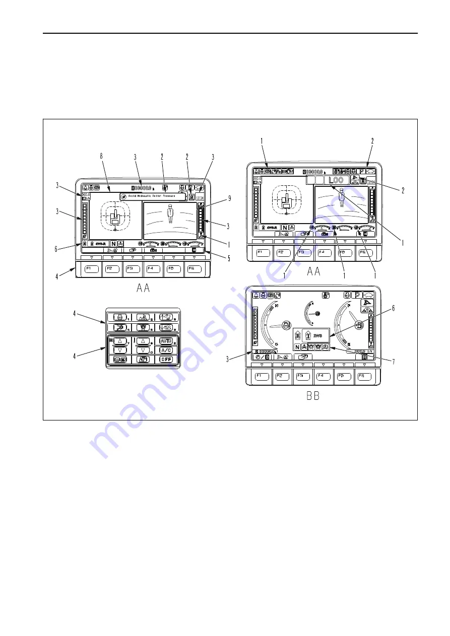
RKA60980
AA: Display with KomVision and camera - BB: Display with gauges only (street mode activated)
(1) Warning display
(2) Pilot display
(3) Service meter
(4) Monitor switch area
(5) Guidance icon display
(6) Steering display
(7) Street mode display
(8) KomVision Display
(9) Camera display
REMARK
• For the user menu used for setting various items of the machine on the machine monitor, see “USER
MENU DISPLAY SWITCH”.
• One of the features of liquid crystal display panels is that there may be black spots (spots that do not light
up) or white spots (spots that stay lit) on the screen. If there are less than 10 black or white spots, this is not
a fault or defect.
• If environmental temperature of the machine monitor is high, brightness may be automatically reduced to
protect the liquid crystal display. However, it is not abnormal.
OPERATION
EXPLANATION OF COMPONENTS
3-9
WENAM00130
Summary of Contents for PW118MR-11
Page 2: ......
Page 9: ...Do not repeatedly handle and lift loads FOREWORD VIBRATION LEVEL 1 7 WENAM00130...
Page 22: ...WENAM00130...
Page 25: ...LOCATION OF SAFETY LABELS RKA64590 SAFETY SAFETY LABELS 2 3 WENAM00130...
Page 72: ...WENAM00130...
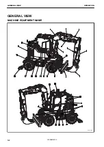
Page 74: ...GENERAL VIEW MACHINE EQUIPMENT NAME RKA61930 GENERAL VIEW OPERATION 3 2 WENAM00130...
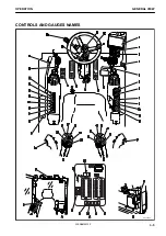
Page 77: ...CONTROLS AND GAUGES NAMES RKA62690 OPERATION GENERAL VIEW 3 5 WENAM00130...
Page 168: ...SWITCHES RKA63060 EXPLANATION OF COMPONENTS OPERATION 3 96 WENAM00130...
Page 328: ...WENAM00130...
Page 412: ...WENAM00130...
Page 413: ...SPECIFICATIONS 5 1 WENAM00130...
Page 445: ...REPLACEMENT PARTS 7 1 WENAM00130...
Page 461: ......
Page 462: ......


