INSTRUMENTS AND CONTROLS
86
4 - AUXILIARY HYDRAULIC KIT CONTROL PEDAL
(IF INSTALLED)
CAUTION
q
The procedures to be followed to use any control sy-
stems different from the ISO and OPTION PATTERNS
are described in section "OPTIONAL EQUIPMENT" (See
"6.5 HAND & FOOT CONTROL SYSTEM"). Carefully read
and be sure to understand the contents of this section
before using the machine.
WARNING
q
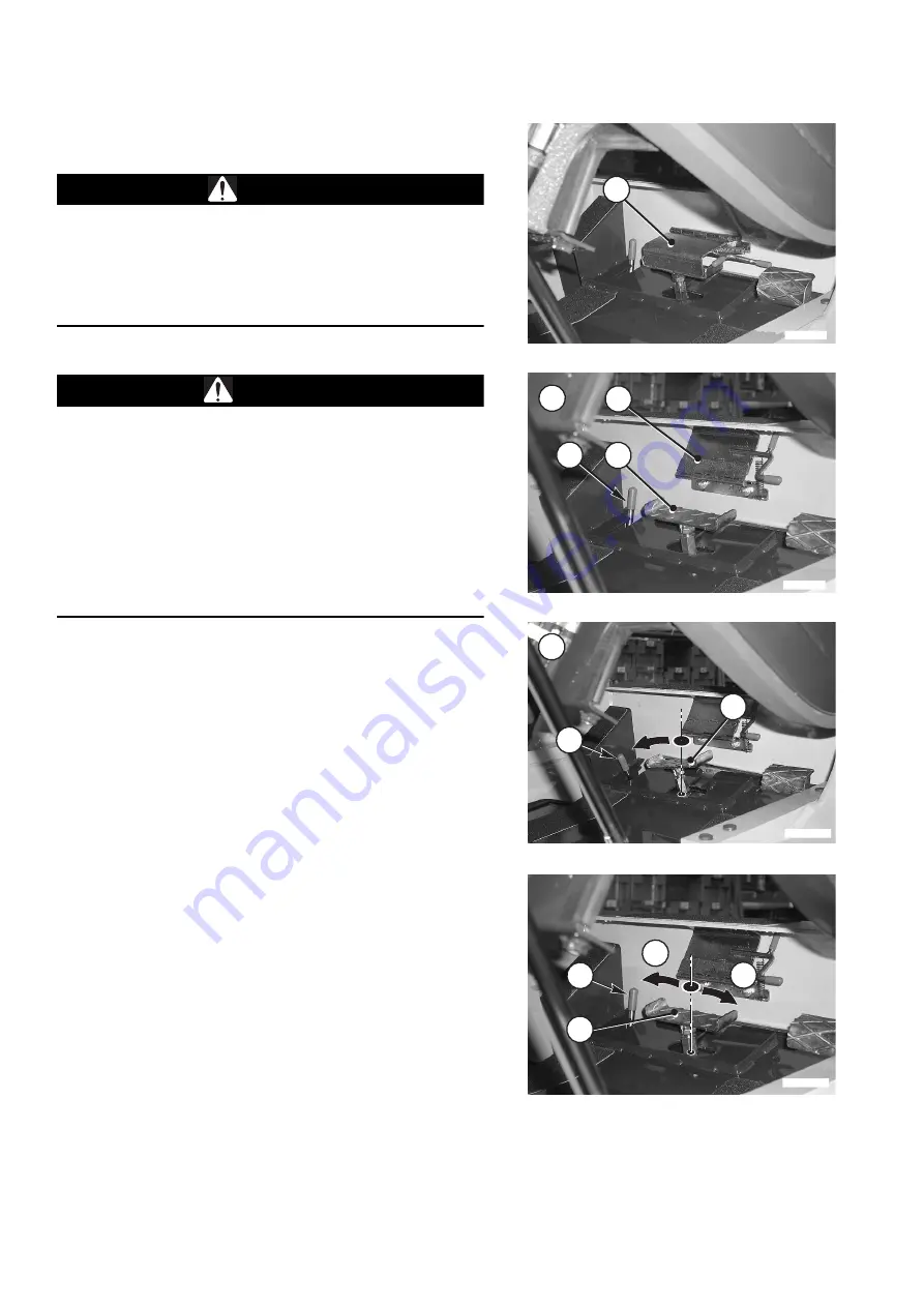
Always apply the safety guard (2) when the use of this
control is not required, during travel and when parking
the machine.
q
When installing any hydraulic control equipment, make
sure that the control pedal (1) is always in neutral posi-
tion and covered by the safety guard (2).
q
Never set the control pedal in the "maximum flow" posi-
tion (B), unless the machine is stationary, with raised sa-
fety bars, and the operator is seated in driving position
with fastened safety belt.
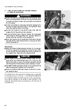
The pedal (1) controls the opening and closing of the oil flow to
the equipment and has three fixed positions (left, neutral, ri-
ght).
NOTE
q
To use the pedal (1), lift the safety guard (2).
1 - Neutral position (A) (HYDRAULIC CIRCUIT CLOSED).
When the pedal is in this position, it isn't possible to use
the optional equipment in any way.
2 - Pressed pedal (B) (HYDRAULIC CIRCUIT OPEN)
When the pedal is pressed with the left side of the foot
and locked in this position with the lever (3), a continuous
oil flow is delivered to the equipment (excavator, demoli-
tion hammer, asphalt cutter, etc.).
To release the pedal (1) and set it in neutral or horizontal
position, push the locking lever (3) forward as indicated in
the figure (A).
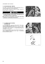
3 - Bidirectional flow position.
The pedal is also used to control the oil flow to the equip-
ment with bidirectional hydraulic circuit (multi-purpose
buckets, drills, asphat cutters, etc.). Shift the locking lever
(3) to the release position and press the pedal (1) to posi-
tion L or R to control the oil flow to the equipment. The
quantity of oil conveyed in each direction is proportional to
the pressure exerted on the pedal.
RKAB1530
2
RWAA12660
B
3
1
2
1
A
RKAB1540
3
RWAA12670
3
L
R
1
Summary of Contents for SK820-5 turbo
Page 2: ......
Page 17: ...SAFETY AND ACCIDENT PREVENTION 15...
Page 19: ...SAFETY NOISE AND VIBRATION PLATES 17 RWA00010 RWA37020...
Page 21: ...SAFETY NOISE AND VIBRATION PLATES 19 RWA37040 RWA00010 RWA00020...
Page 53: ...THE MACHINE AND ITS OPERATIONS 51...
Page 62: ...GENERAL VIEWS 60 10 Left console switches 11 Right console switches RWAA9720 11 RWAA11260 10...
Page 154: ...152 PAGE INTENTIONALLY LEFT BLANK...
Page 155: ...MAINTENANCE 153...
Page 205: ...TECHNICAL SPECIFICATIONS 203...
Page 213: ...TECHNICAL DATA 211 SOLID TYRES SIZE MAKE 10x16 5 AIR BOSS...
Page 214: ...212 PAGE INTENTIONALLY LEFT BLANK...
Page 215: ...AUTHORISED OPTIONAL EQUIPMENT 213...
Page 242: ...240 PAGE INTENTIONALLY LEFT BLANK...
Page 243: ......
Page 244: ...2004 KOMATSU UTILITY EUROPE S p A All Rights Reserved Printed in Europe...

