INSTRUMENTS AND CONTROLS
90
9 - "HIGH FLOW" HYDRAULIC SYSTEM CONTROL
(3 LINES) (IF INSTALLED)
WARNING
q
Avoid connecting any equipment to the hydraulic lines
before said equipment has been correctly installed from
a mechanical point of view and secured to the machine
front coupling.
q
Avoid connecting any manually-controlled equipment or
tool (for example, hand hammer) to the hydraulic lines
while the equipment/tool is working.
q
Connect the hydraulic and electric lines only with the
engine off and the parking brake applied.
q
To avoid serious injury, always operate the equipment
while seated in driving position. Do not allow anyone to
get too close the machine or the equipment.
q
Read the contents of the equipment instruction manual
carefully before using the machine or carrying out main-
tenance operations.
IMPORTANT
q
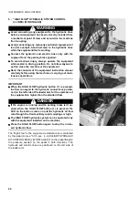
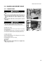
When the HIGH FLOW hydraulic button (1) is pressed,
the flow conveyed to the hydraulic connections positio-
ned on the left side of the loader arm for the operation of
the equipment is higher than the standard flow.
DANGER
q
If the engine is running and the parking brake isn't ap-
plied, when the HIGH FLOW button (1) is pressed the
LED on the button comes on and the hydraulic oil flow
rate through the front auxiliary rapid couplings is high.
q
The HIGH FLOW hydraulic system can be operated only
with the equipment installed on the machine.
q
Press the HIGH FLOW button again to stop the increa-
sed hydraulic flow.
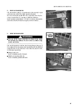
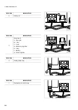
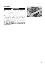
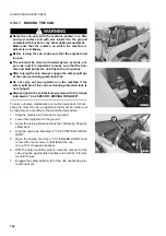
The "High Flow" to the equipment is bidirectional, is controlled
by the pedal (A) (see "3.3.5 pos. 4 - AUXILIARY HYDRAULIC
KIT CONTROL PEDAL (IF INSTALLED)") and is proportional to
the pressure exerted on the pedal in both directions. The
hydraulic and electric lines are positioned on the left side of
the loader arm.
RWAA10480
1
RKAB1370
A
RKAB01350
Summary of Contents for SK820-5 turbo
Page 2: ......
Page 17: ...SAFETY AND ACCIDENT PREVENTION 15...
Page 19: ...SAFETY NOISE AND VIBRATION PLATES 17 RWA00010 RWA37020...
Page 21: ...SAFETY NOISE AND VIBRATION PLATES 19 RWA37040 RWA00010 RWA00020...
Page 53: ...THE MACHINE AND ITS OPERATIONS 51...
Page 62: ...GENERAL VIEWS 60 10 Left console switches 11 Right console switches RWAA9720 11 RWAA11260 10...
Page 154: ...152 PAGE INTENTIONALLY LEFT BLANK...
Page 155: ...MAINTENANCE 153...
Page 205: ...TECHNICAL SPECIFICATIONS 203...
Page 213: ...TECHNICAL DATA 211 SOLID TYRES SIZE MAKE 10x16 5 AIR BOSS...
Page 214: ...212 PAGE INTENTIONALLY LEFT BLANK...
Page 215: ...AUTHORISED OPTIONAL EQUIPMENT 213...
Page 242: ...240 PAGE INTENTIONALLY LEFT BLANK...
Page 243: ......
Page 244: ...2004 KOMATSU UTILITY EUROPE S p A All Rights Reserved Printed in Europe...

