OPERATION
Explanation of components
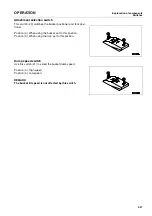
Safety bar
3-43
Safety bar
0.
WARNING
When carrying out maintenance or transporting the machine, always set the safety bar to the LOCK
position.
Always remove the safety bar for travel operations. If it is not removed, the steering wheel cannot be
used for steering, and this may lead to serious damage or injury.
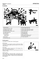
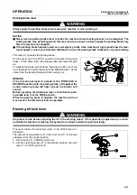
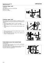
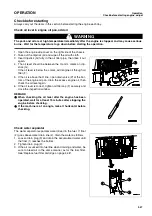
This is a device used to lock the front and rear frames during
maintenance or when transporting the machine. It prevents the
front and rear frames from articulating.
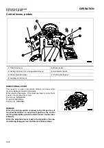
Towing pin
0.
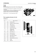
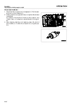
1. Align protrusion (1) in the towing pin with groove (2) in the
counterweight, then insert the pin and turn it 180°.
2. To prevent the towing pin from turning, fold the handle of the
towing pin and set it in position.
Reverse this operation to remove the pin.
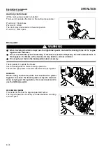
Grease pump
0.
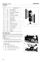
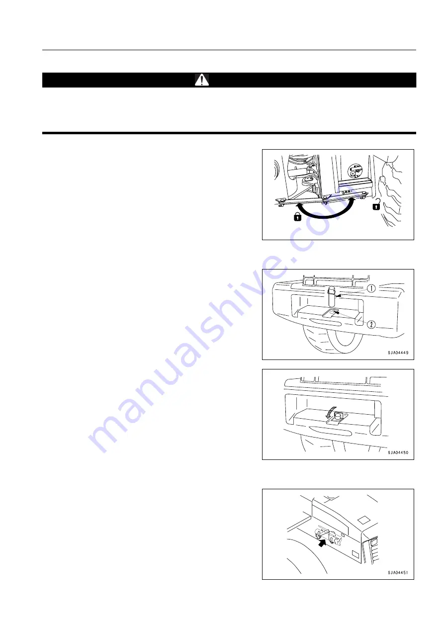
The grease pump is stowed inside the left engine side cover at
the rear of the machine.
After using the pump, wipe off all the grease stuck to the pump,
set it in the clamp inside the cover, then fit the chain to the
clamp to prevent the pump from moving.
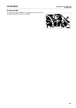
In addition, form the rubber ring into a figure of 8 as shown in
the diagram on the right, and secure in position.
9EA04780A
Free
Lock
Summary of Contents for WA250PT-5H
Page 2: ......
Page 3: ...FOREWORD 11...
Page 16: ...Contents FOREWORD 1 14...
Page 24: ...SAFETY 2 2...
Page 58: ...Precautions with tires SAFETY Precautions when storing tires 2 36...
Page 60: ...OPERATION 3 2...
Page 233: ...TECHNICAL DATA 45...
Page 235: ...TECHNICAL DATA Technical data 5 3...
Page 250: ...Central lubrication system ATTACHMENTS OPTIONS 6 14...
Page 251: ...INDEX 67...
Page 252: ...INDEX 7 2...
Page 255: ...Index 7 5...


