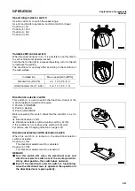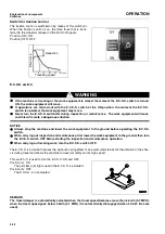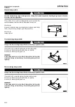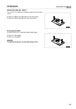
Explanation of components
OPERATION
Control levers, pedals
3-38
Control levers, pedals
0.
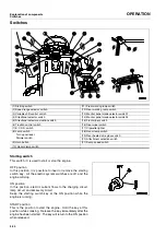
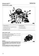
DIRECTIONAL LEVER
0.
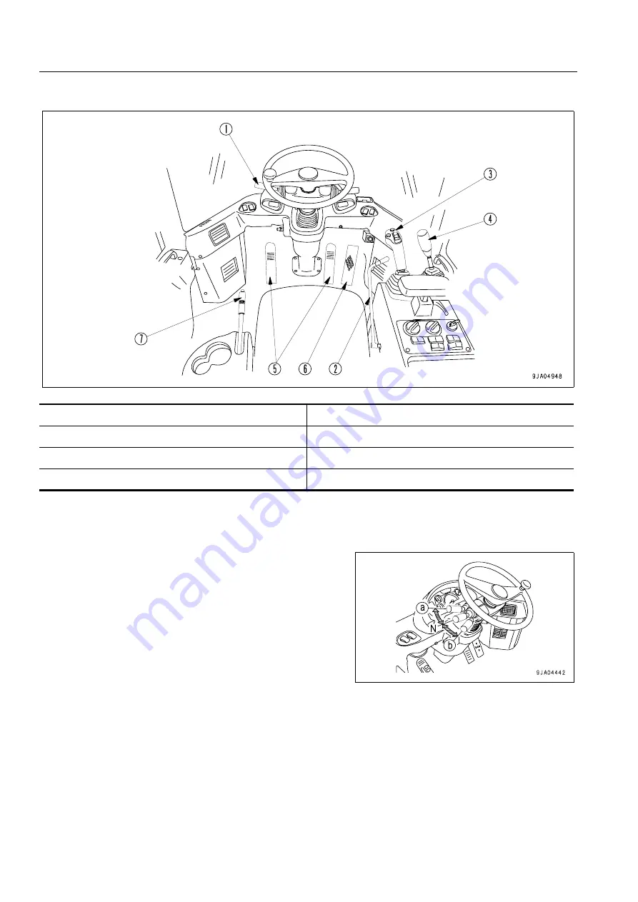
This lever (1) is used to switch the direction of travel of the
machine between forward and reverse.
When starting the engine, if the directional lever is not at the N
position, the engine will not start.
Position (a): FORWARD
Position N: NEUTRAL
Position (b): REVERSE
REMARK
When the starting switch is turned to the ON position, if
the directional lever is not at the N position, the central
warning lamp lights up and the alarm buzzer sounds inter-
mittently.
When the directional lever is set to the N position, the cen-
tral warning lamp goes out and the alarm buzzer stops.
(1) Directional lever
(5) Brake pedal
(2) Safety lock lever (for work equipment lever)
(6) Accelerator pedal
(3) Work equipment lever
(7) Parking brake lever
(4) Auxiliary control lever
Summary of Contents for WA250PT-5H
Page 2: ......
Page 3: ...FOREWORD 11...
Page 16: ...Contents FOREWORD 1 14...
Page 24: ...SAFETY 2 2...
Page 58: ...Precautions with tires SAFETY Precautions when storing tires 2 36...
Page 60: ...OPERATION 3 2...
Page 233: ...TECHNICAL DATA 45...
Page 235: ...TECHNICAL DATA Technical data 5 3...
Page 250: ...Central lubrication system ATTACHMENTS OPTIONS 6 14...
Page 251: ...INDEX 67...
Page 252: ...INDEX 7 2...
Page 255: ...Index 7 5...

