


OPERATION
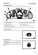
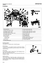
Explanation of components
Machine monitor
3-27
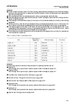
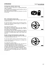
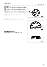
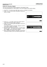
Reset method for filter, oil replacement time
0.
The filter and oil replacement time is displayed on the character display, so if the filter and oil have been replaced,
reset the filter and oil change time.
1. Press the (
) of monitor panel mode selector switch 1, and display the odometer.
2. Press (>) or (<) of monitor panel mode selector switch 2 and
display “MAINTENANCE MONITOR“.
3. Press the (
) of monitor mode selector switch 1.
The item is displayed, and then the replacement interval is
displayed in the center and the number of times of replace-
ment is displayed on the right in turn for 3 seconds each.
4. Press the (>) or (<) of monitor panel mode selector switch 2
to display the item (filter or oil) which has reached the
replacement time.
5. Press the (
) of monitor mode selector switch 1.
[RESET] and [YES <> NO] are displayed in turn.
6. When resetting the replacement time, press (>) or (<) of
monitor panel mode selector switch 2, align the cursor with
“YES“, then press (
) of machine monitor mode selector
switch 1. It will reset and return to the previous screen.
To abort, align the cursor with “NO“, then press (
) of moni-
tor panel mode selector switch 1.
7. When resetting the replacement time for another item, carry
out the procedure from Step 4. After completing, press (
)
of monitor panel mode selector switch 1 twice or turn the
starting switch OFF.
Summary of Contents for WA250PT-5H
Page 2: ......
Page 3: ...FOREWORD 11...
Page 16: ...Contents FOREWORD 1 14...
Page 24: ...SAFETY 2 2...
Page 58: ...Precautions with tires SAFETY Precautions when storing tires 2 36...
Page 60: ...OPERATION 3 2...
Page 233: ...TECHNICAL DATA 45...
Page 235: ...TECHNICAL DATA Technical data 5 3...
Page 250: ...Central lubrication system ATTACHMENTS OPTIONS 6 14...
Page 251: ...INDEX 67...
Page 252: ...INDEX 7 2...
Page 255: ...Index 7 5...


