MAINTENANCE
SERVICE PROCEDURE
4-55
EVERY 2000 HOURS SERVICE
4
Maintenance for every 50, 100, 250, 500 and 1000 hours service should be carried out at the same time.
CHANGE OIL IN HYDRAULIC TANK, REPLACE HYDRAULIC FILTER ELEMENT
4
WARNING
q
The parts and oil are at high temperature after the engine is stopped, and may cause burns. Wait for
the temperature to go down before starting the work.
q
When removing the oil filler cap, turn it slowly to release the internal pressure, then remove it.
q
Refill capacity: 89 liters (25.51 US gal)
1.
Lower the bucket horizontally to the ground and apply the parking brake, then stop the engine.
2.
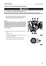
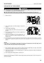
Remove covers (1) and (2).
3.
Keep grip (3) pulled, then turn oil filler cap (F) counter-
clockwise and remove it.
4.
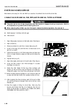
Set a container to catch the oil under drain plug (P).
5.
After removing drain plug (P), open drain valve (4) and
drain the oil.
6.
After draining the oil, close drain valve (4) and install drain
plug (P).
7.
Using a filter wrench, turn cartridge (5) to the left to remove
it.
8.
Clean the filter holder, fill the new filter cartridge with oil,
then coat the seal and thread of the filter cartridge with oil
(or coat thinly with grease) and install.
When installing the seal, tighten it until its surface comes to
contact with the filter holder, then tighten it 1/3 turn more.
9.
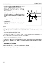
Refill the specified quantity of oil through oil filler (F).
10. Check that the hydraulic oil is at the specified level. For
details, see “CHECK OIL LEVEL IN HYDRAULIC TANK,
ADD OIL (4-41)“.
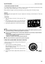
11. Run the engine at low idling, and extend and retract the steering, bucket, and lift arm cylinders 4 to 5 times.
Be careful not to operate the cylinder to the end of its stroke (stop approx.100 mm (3.9 in) before the end of
stroke).
NOTICE
If the engine is run immediately at high speed or the cylinder is operated to the end of its stroke, the air
inside the cylinder will cause damage to the piston packing.
12. Next, operate the steering, bucket, and lift arm cylinders to the end of their stroke 3 to 4 times, then stop the
engine and loosen fillercap to bleed the air from the hydraulic tank.
Summary of Contents for WA320-5H
Page 2: ...FOREWORD 11...
Page 17: ...CONTENTS FOREWORD 1 16...
Page 23: ...CE CONFORMING EQUIPMENT FOREWORD 1 22...
Page 24: ...SAFETY 12...
Page 25: ...SAFETY 2 2...
Page 60: ...OPERATION 13...
Page 181: ...TROUBLESHOOTING OPERATION 3 122...
Page 182: ...MAINTENANCE 14...
Page 243: ...SERVICE PROCEDURE MAINTENANCE 4 62...
Page 244: ...TECHNICAL DATA 15...
Page 246: ...TECHNICAL DATA TECHNICAL DATA 5 3...
Page 248: ...ATTACHMENTS OPTIONS 16...
Page 313: ...CENTRAL LUBRICATION SYSTEM ATTACHMENTS OPTIONS 6 66...
Page 314: ...INDEX 17...
Page 315: ...INDEX 7 2...
Page 318: ...NOTES 18...
Page 319: ...NOTES NOTES 8 2 NOTES 8...
Page 320: ...NOTES NOTES 8 3...
Page 321: ...2003 Komatsu Hanomag GmbH All Rights Reserved Printed in Europe 10 2003...

