EXPLANATION OF COMPONENTS
OPERATION
3-40
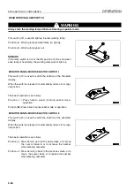
SAFETY LOCK LEVER (FOR WORK EQUIPMENT LEVER)
WARNING
q
Before leaving the operator's seat, set the safety lock lever securely to the LOCK position. If the
safety lock lever is not at the LOCK position, and work equipment control lever is touched by mistake,
it may lead to a serious accident.
q
If the safety lock lever is not placed securely at the LOCK position, the work equipment control lever
may move, and this may lead to a serious accident or personal injury. Check that the lever is in the
LOCK position.
q
When operating the safety lock lever, check that the work equipment control lever is held securely at
the HOLD position.
q
When pulling up or pushing down the safety lock lever, be careful not to touch work equipment control
lever.
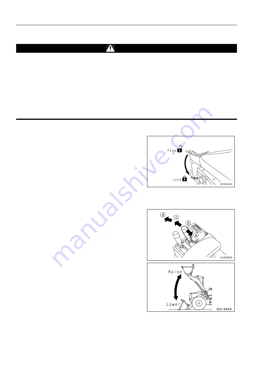
This lever (2) is a lock device for the work equipment control
lever.
Push the safety lock lever down to lock it.
REMARK
If the safety lock lever is at the LOCK position, the work equip-
ment will not move even when the work equipment control
lever is operated.
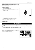
LIFT ARM CONTROL LEVER
This lever (3) is used to operate the lift arm.
NOTICE
Do not use the FLOAT position when lowering the bucket.
Use the FLOAT position when leveling, see “LEVELING
OPERATIONS (3-89)“.
Position (a): RAISE
When the lift arm control lever is pulled further
from the RAISE position, the lever is stopped in
this position until the lift arm reaches the preset
position of the kickout, and the lever is returned to
the HOLD position.
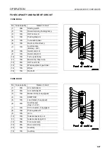
Position (b): HOLD
The lift arm is kept in the same position.
Position (c): LOWER
Position (d): FLOAT
The lift arm moves freely under external force.
Summary of Contents for WA320-5H
Page 2: ...FOREWORD 11...
Page 17: ...CONTENTS FOREWORD 1 16...
Page 23: ...CE CONFORMING EQUIPMENT FOREWORD 1 22...
Page 24: ...SAFETY 12...
Page 25: ...SAFETY 2 2...
Page 60: ...OPERATION 13...
Page 181: ...TROUBLESHOOTING OPERATION 3 122...
Page 182: ...MAINTENANCE 14...
Page 243: ...SERVICE PROCEDURE MAINTENANCE 4 62...
Page 244: ...TECHNICAL DATA 15...
Page 246: ...TECHNICAL DATA TECHNICAL DATA 5 3...
Page 248: ...ATTACHMENTS OPTIONS 16...
Page 313: ...CENTRAL LUBRICATION SYSTEM ATTACHMENTS OPTIONS 6 66...
Page 314: ...INDEX 17...
Page 315: ...INDEX 7 2...
Page 318: ...NOTES 18...
Page 319: ...NOTES NOTES 8 2 NOTES 8...
Page 320: ...NOTES NOTES 8 3...
Page 321: ...2003 Komatsu Hanomag GmbH All Rights Reserved Printed in Europe 10 2003...


