OPERATION
EXPLANATION OF COMPONENTS
3-49
AIR CONDITIONER
3
By taking fresh air into the cab through a filter, it is possible to raise the pressure inside the cab. This makes it pos-
sible to provide a pleasant working environment even on dusty jobsites.
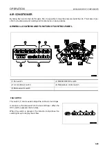
GENERAL LOCATIONS AND FUNCTION OF CONTROL PANEL
3
FAN SWITCH
This switch (1) can be used to adjust the air flow to four stages.
It also acts as the main switch for the air conditioner. When the
OFF switch is pressed, the fan stops.
When the switch is pressed, the indicator lamp above the
switch lights up to display the air flow.
(1) Fan switch
(4) FRESH/RECIRC switch
(2) Air conditioner switch
(5) Temperature control switch
(3) Mode selector switch
Summary of Contents for WA320-5H
Page 2: ...FOREWORD 11...
Page 17: ...CONTENTS FOREWORD 1 16...
Page 23: ...CE CONFORMING EQUIPMENT FOREWORD 1 22...
Page 24: ...SAFETY 12...
Page 25: ...SAFETY 2 2...
Page 60: ...OPERATION 13...
Page 181: ...TROUBLESHOOTING OPERATION 3 122...
Page 182: ...MAINTENANCE 14...
Page 243: ...SERVICE PROCEDURE MAINTENANCE 4 62...
Page 244: ...TECHNICAL DATA 15...
Page 246: ...TECHNICAL DATA TECHNICAL DATA 5 3...
Page 248: ...ATTACHMENTS OPTIONS 16...
Page 313: ...CENTRAL LUBRICATION SYSTEM ATTACHMENTS OPTIONS 6 66...
Page 314: ...INDEX 17...
Page 315: ...INDEX 7 2...
Page 318: ...NOTES 18...
Page 319: ...NOTES NOTES 8 2 NOTES 8...
Page 320: ...NOTES NOTES 8 3...
Page 321: ...2003 Komatsu Hanomag GmbH All Rights Reserved Printed in Europe 10 2003...


