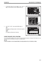
2.
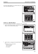
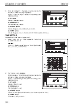
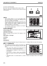
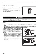
Adjust the brightness by using the switch panel.
The brightness can be adjusted individually in the day and
night modes.
(1) Menu switch
Brightness is set to default.
(2) UP switch
Brightness increases. (Moves the indicator to the right by
one division.)
(3) DOWN switch
Brightness decreases. (Moves the indicator to the left by
one division.)
(4) RETURN switch
Cancels the change and returns to “Monitor Setting” menu.
(5) ENTER switch
Accepts the change and then returns to “Monitor Setting”
menu.
REMARK
When the screen is adjusted while the lamp switch is turned
off, the brightness in the day mode can be adjusted.
Turn on the lamp switch, then adjust the screen when the moni-
tor brightness selector switch is set to the night mode, the
brightness in the night mode can be adjusted.
The brightness of night illumination for the switch panel and op-
eration switches are adjusted synchronously with the bright-
ness of the machine monitor.
CLOCK ADJUSTMENT
On the clock adjustment menu, you can change the setting of
the clock displayed on the standard screen.
The following items can be changed.
“GPS Synchronization”
“Calendar”
“Time”
“12hour or 24hour Mode”
“Daylight Saving Time”
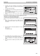
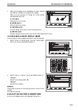
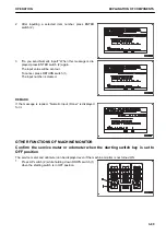
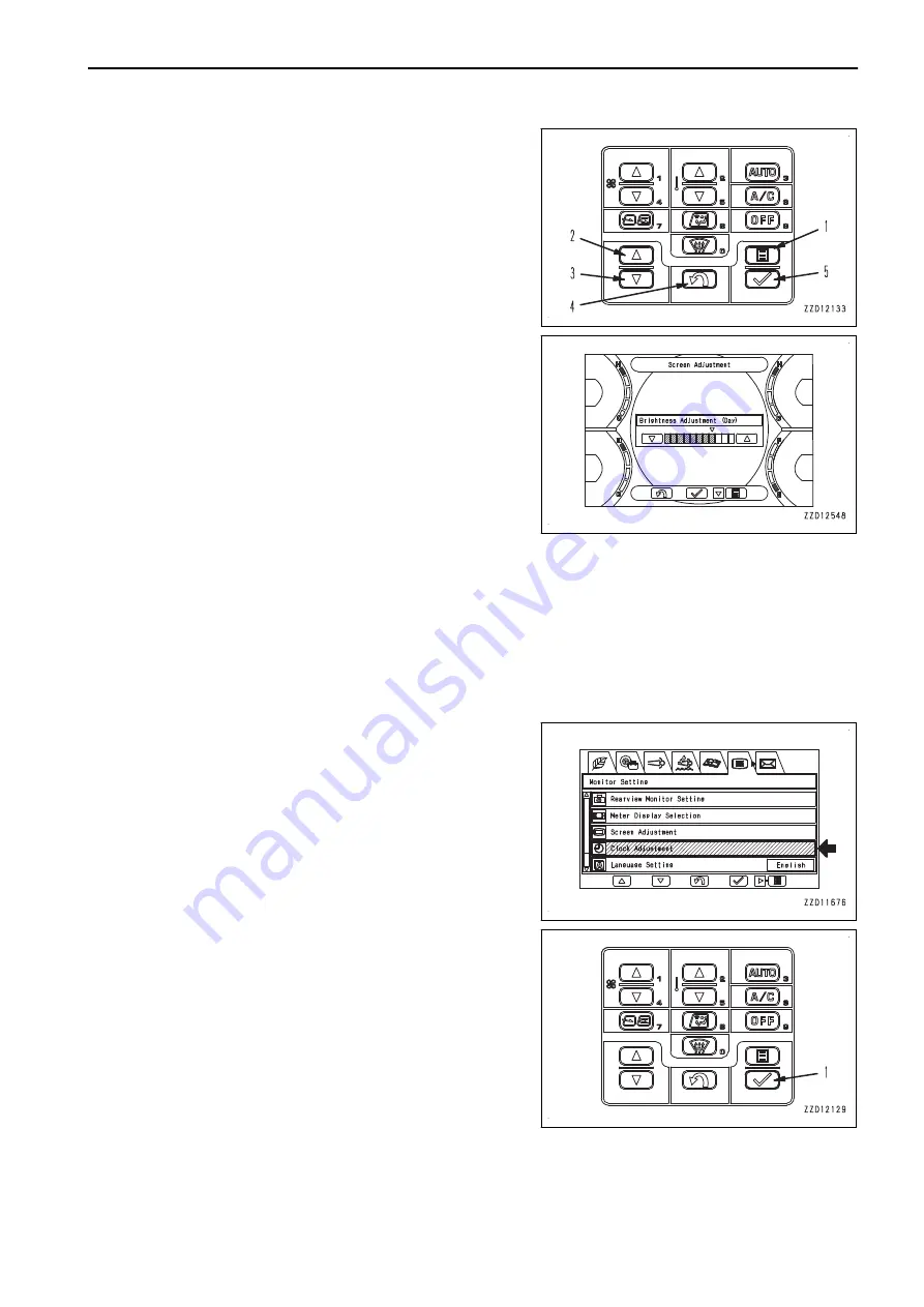
Select “Clock Adjustment” on the “Monitor Setting” menu
screen, then press ENTER switch (1).
REMARK
After a long-term storage of the machine, Calendar and Time
are reset, so you must readjust them.
When the “GPS Synchronization” is set to “ON”, the above are
automatically readjusted.
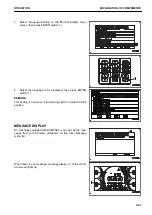
GPS SYNCHRONIZATION
On the machines equipped with KOMTRAX, you can configure automatic setting of the machine monitor's date
and time in accordance with the GPS's clock.
OPERATION
EXPLANATION OF COMPONENTS
3-81
Summary of Contents for WA480-8
Page 2: ......
Page 19: ...Distributor name Address Phone Fax Service personnel FOREWORD PRODUCT INFORMATION 1 17...
Page 29: ...LOCATION OF SAFETY LABELS SAFETY SAFETY LABELS 2 3...
Page 159: ...SWITCHES 1 ECSS switch 2 Front working lamp switch OPERATION EXPLANATION OF COMPONENTS 3 91...
Page 302: ...Securing position Fixing angle A 61 B 53 C 33 D 38 TRANSPORTATION OPERATION 3 234...
Page 324: ......
Page 397: ...Viewed from the rear side of the machine MAINTENANCE MAINTENANCE PROCEDURE 4 73...
Page 402: ......
Page 403: ...SPECIFICATIONS 5 1...
Page 406: ......
Page 422: ......
Page 423: ...REPLACEMENT PARTS 7 1...
Page 439: ......

