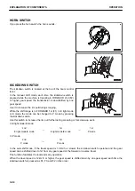
Use the hazard lamp switch when you need to park the ma-
chine on a road due to machine failure or during emergency
only.
Position (A): The turn signal lamps and the turn signal pilot
lamp flash.
Position (B):The lamps go out.
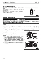
DIRECTIONAL SELECTOR SWITCH
(if equipped)
The directional selector switch is used to set the travel direction
to FORWARD, NEUTRAL, and REVERSE.
Position (F): FORWARD
Position (N): NEUTRAL
Position (R): REVERSE
Before using this switch to change the travel direction, set the
directional lever to NEUTRAL position and set the directional
selector enable switch of R.H. switch panel to “enable” position.
REMARK
Do not maintain the directional selector switch at the intermedi-
ate position between positions (F) and (N), or between posi-
tions (N) and (R). Such practice sounds the alarm buzzer and
sets the transmission in NEUTRAL.
TRANSMISSION CUT-OFF SWITCH
k
k
WARNING
When starting the machine off an uphill, turn the transmission cut-off switch to OFF position, depress
the accelerator pedal while depressing brake pedal and then release the brake pedal gradually to allow
the machine to start off. This prevents the machine from rolling back.
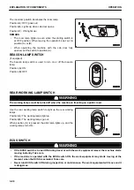
Press position (A) of the transmission cut-off switch to set it ON
or OFF.
If you release your hand from the switch, it automatically re-
turns to its original position.
Each time position (A) is pressed, the transmission cut-off func-
tion switches between ON and OFF. When this function is
turned on, the pilot lamps light up on the monitor and on switch
(A) position, and the transmission becomes NEUTRAL at the
adjusted brake pedal pressing position.
Normally, keep the switch at ON position.
For details of the cut-off position adjustment procedure, see “METHOD FOR ADJUSTING TRANSMISSION
CUT-OFF POSITION (3-196)”.
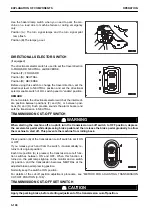
TRANSMISSION CUT-OFF SET SWITCH
k
k
CAUTION
Apply the parking brake, before starting adjustment of the transmission cut-off position.
EXPLANATION OF COMPONENTS
OPERATION
3-100
Summary of Contents for WA480-8
Page 2: ......
Page 19: ...Distributor name Address Phone Fax Service personnel FOREWORD PRODUCT INFORMATION 1 17...
Page 29: ...LOCATION OF SAFETY LABELS SAFETY SAFETY LABELS 2 3...
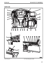
Page 159: ...SWITCHES 1 ECSS switch 2 Front working lamp switch OPERATION EXPLANATION OF COMPONENTS 3 91...
Page 302: ...Securing position Fixing angle A 61 B 53 C 33 D 38 TRANSPORTATION OPERATION 3 234...
Page 324: ......
Page 397: ...Viewed from the rear side of the machine MAINTENANCE MAINTENANCE PROCEDURE 4 73...
Page 402: ......
Page 403: ...SPECIFICATIONS 5 1...
Page 406: ......
Page 422: ......
Page 423: ...REPLACEMENT PARTS 7 1...
Page 439: ......


