1.
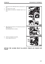
Pull down engine side cover (1).
2.
Raise lock lever (2) and turn it, then lower the lock lever at
FREE position (F).
Rear full-length fender (3) is unlocked.
3.
Hold handle (4) of rear full-length fender (3) and slide it in-
ward, and return the rear full-length (3) fender to its origi-
nal position.
GREASE PUMP HOLDER
(if equipped)
The grease pump is installed to the holder in the toolbox on the
inside of the left step of the machine. After using the pump,
wipe off the grease from its outside, and install it in position.
Insert the grease pump into the holder and fix it with the rubber
band.
FIRE EXTINGUISHER
(if equipped)
EXPLANATION OF COMPONENTS
OPERATION
3-122
Summary of Contents for WA480-8
Page 2: ......
Page 19: ...Distributor name Address Phone Fax Service personnel FOREWORD PRODUCT INFORMATION 1 17...
Page 29: ...LOCATION OF SAFETY LABELS SAFETY SAFETY LABELS 2 3...
Page 159: ...SWITCHES 1 ECSS switch 2 Front working lamp switch OPERATION EXPLANATION OF COMPONENTS 3 91...
Page 302: ...Securing position Fixing angle A 61 B 53 C 33 D 38 TRANSPORTATION OPERATION 3 234...
Page 324: ......
Page 397: ...Viewed from the rear side of the machine MAINTENANCE MAINTENANCE PROCEDURE 4 73...
Page 402: ......
Page 403: ...SPECIFICATIONS 5 1...
Page 406: ......
Page 422: ......
Page 423: ...REPLACEMENT PARTS 7 1...
Page 439: ......


