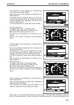
engine power restoration procedure, refer to the section of “Temporary Restoration from Inducement” in this
manual. Once in “Severe Inducement” and it becomes necessary to restore engine power, use the engine
power restoration function to move the machine to a safe place and add DEF.
Inducement strategy when abnormalities are detected in the Urea SCR System
devices (Except abnormalities in the KDPF and the EGR system)
If any abnormality is detected in the DEF quality or in the Urea SCR system, the Inducement strategy is activa-
ted.
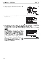
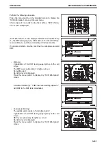
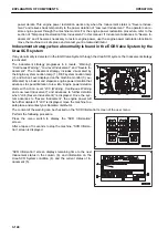
The inducement strategy progresses in 4 levels, “Warning”,
“Continuous Warning”, “Low level Inducement” and “Severe In-
ducement”. The Inducement strategy includes visual alert by
the DEF system caution lamp (1), and Action Level displayed
on the machine monitor (2), and the audible alert by a buzzer
and stepwise engine power deration that advances to speed
limitation to low idle. Engine power deration starts with Action
Level “L03 (Low level Inducement)” and advances to further
deration when “L04 (Severe Inducement)” is displayed. If “L03”
is displayed, move the machine to a safe place and contact
your Komatsu distributor.
The content of the warning can be checked on the “SCR Information” screen of the user menu.
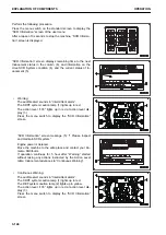
Perform the following procedure.
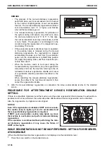
Press the menu switch on the standard screen to display the
“SCR Information” screen of the user menu.
After a lapse of 3 seconds to stop the machine, “SCR Informa-
tion” screen is displayed.
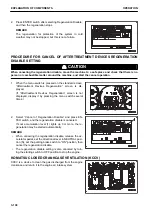
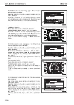
“SCR Information” screen displays remaining time to the next
Inducement status in the column (5), and information on the
Urea SCR System condition (3), and the current status of In-
ducement (4).
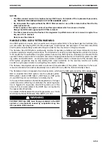
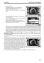
• Warning:
No audible alert.
The DEF system caution lamp (1) lights up in yellow.
Note: Action Level “L01” once shows up in yellow on the
machine monitor (2) for two seconds and goes out.
Press the menu switch to display the “SCR Information”
screen.
OPERATION
EXPLANATION OF COMPONENTS
3-143
Summary of Contents for WA480-8
Page 2: ......
Page 19: ...Distributor name Address Phone Fax Service personnel FOREWORD PRODUCT INFORMATION 1 17...
Page 29: ...LOCATION OF SAFETY LABELS SAFETY SAFETY LABELS 2 3...
Page 159: ...SWITCHES 1 ECSS switch 2 Front working lamp switch OPERATION EXPLANATION OF COMPONENTS 3 91...
Page 302: ...Securing position Fixing angle A 61 B 53 C 33 D 38 TRANSPORTATION OPERATION 3 234...
Page 324: ......
Page 397: ...Viewed from the rear side of the machine MAINTENANCE MAINTENANCE PROCEDURE 4 73...
Page 402: ......
Page 403: ...SPECIFICATIONS 5 1...
Page 406: ......
Page 422: ......
Page 423: ...REPLACEMENT PARTS 7 1...
Page 439: ......

