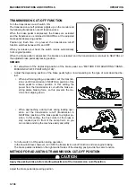
REMARK
The boom “RAISE” operation and the bucket “TILT” operation can be performed even if the auto-digging is
in operation. When performing the digging work while the priority is given to the productivity, you can per-
form the “RAISE” or “TILT” operation more quickly by operating the work equipment control lever.
• When setting the auto-kickdown to OFF
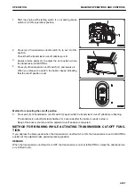
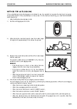
1) Set the auto-digging switch to ON.
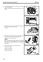
2) While driving the machine forward, lower the bucket edge
to height (a) of approximately 30 cm above the ground.
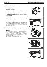
3) Press the kickdown switch to shift down the gear to FOR-
WARD 1st.
After the speed has been shifted down to FORWARD 1st,
the auto-digging mode starts.
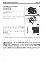
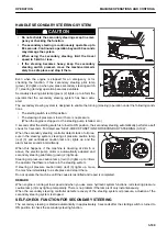
4) Depress the accelerator pedal and thrust the bucket edge
into the stock pile.
The machine starts auto-digging.
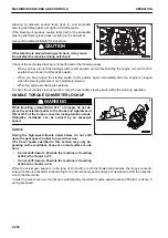
REMARK
• If the travel speed is 3 km/h or less during the auto-
digging mode, the boom may rise automatically.
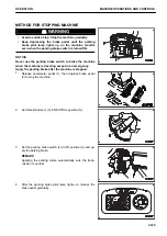
• When the gear speed is fixed to 1st in the manual shift
mode, if the kickdown switch is pressed, the machine
is set in the auto-digging mode.
5) If the bucket is fully tilted, the auto-digging mode is finished.
The auto-digging mode can be cancelled by performing the following operations. When the auto-digging
mode is cancelled, the buzzer “beeps”.
• When the boom is raised beyond the horizontal position
• When the auto-digging switch is set to OFF
• When the boom control lever is set to “LOWER” position
• When the bucket control lever is set to “DUMP” position
• When the work equipment lock switch is pressed to lock the work equipment (the pilot lamp lights up)
• When the directional lever and directional selector switch (if equipped) are set in a position other than
FORWARD (In this case, the buzzer does not sound.)
MACHINE OPERATIONS AND CONTROLS
OPERATION
3-204
Summary of Contents for WA480-8
Page 2: ......
Page 19: ...Distributor name Address Phone Fax Service personnel FOREWORD PRODUCT INFORMATION 1 17...
Page 29: ...LOCATION OF SAFETY LABELS SAFETY SAFETY LABELS 2 3...
Page 159: ...SWITCHES 1 ECSS switch 2 Front working lamp switch OPERATION EXPLANATION OF COMPONENTS 3 91...
Page 302: ...Securing position Fixing angle A 61 B 53 C 33 D 38 TRANSPORTATION OPERATION 3 234...
Page 324: ......
Page 397: ...Viewed from the rear side of the machine MAINTENANCE MAINTENANCE PROCEDURE 4 73...
Page 402: ......
Page 403: ...SPECIFICATIONS 5 1...
Page 406: ......
Page 422: ......
Page 423: ...REPLACEMENT PARTS 7 1...
Page 439: ......

