8.
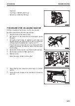
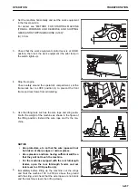
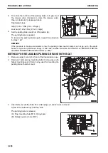
To restore the function of the parking brake, turn grip (3) of
the release valve clockwise to close the release valve,
then turn locknut (2) clockwise to lock.
Tightening torque
Grip (3): 20 ± 5 Nm {2.0 ± 0.5 kgm}
Lock nut (2): 20 ± 5 Nm {2.0 ± 0.5 kgm}
9.
Set the parking brake switch to ON position (A).
The parking brake is applied.
To release the parking brake again, repeat the procedure
in steps 1 to 7.
REMARK
If the pressure in brake accumulator is low, the parking brake caution lamp may not go out or the alarm
buzzer may sound (continuous beep). In this case, release the brake. For details, see “METHOD FOR RE-
LEASING PARKING BRAKE WITH BOLT (3-246)”.
METHOD FOR RELEASING PARKING BRAKE WITH BOLT
1.
Remove plugs (1) and (2) in front of the transmission case.
2.
Remove 2 bolts among mounting bolts (3) (4 pieces), with
higher mounting seat (3 mm), being used for mounting the
parking brake chamber cover.
3.
Insert bolts (3) into the holes from which plugs (1) and (2) were removed.
Screw in the bolts evenly until they stop.
The parking brake is released.
(A): Plug mounting hole (M16: O-ring boss)
(B): Releasing screw hole (M12)
TROUBLES AND ACTIONS
OPERATION
3-246
Summary of Contents for WA480-8
Page 2: ......
Page 19: ...Distributor name Address Phone Fax Service personnel FOREWORD PRODUCT INFORMATION 1 17...
Page 29: ...LOCATION OF SAFETY LABELS SAFETY SAFETY LABELS 2 3...
Page 159: ...SWITCHES 1 ECSS switch 2 Front working lamp switch OPERATION EXPLANATION OF COMPONENTS 3 91...
Page 302: ...Securing position Fixing angle A 61 B 53 C 33 D 38 TRANSPORTATION OPERATION 3 234...
Page 324: ......
Page 397: ...Viewed from the rear side of the machine MAINTENANCE MAINTENANCE PROCEDURE 4 73...
Page 402: ......
Page 403: ...SPECIFICATIONS 5 1...
Page 406: ......
Page 422: ......
Page 423: ...REPLACEMENT PARTS 7 1...
Page 439: ......

