1.
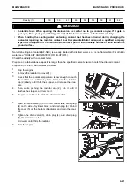
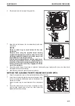
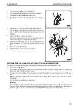
Turn the starting switch to OFF position (A).
2.
Turn the battery disconnect switch key to OFF position.
Check that the system operating lamp is off.
3.
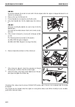
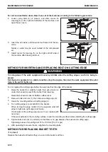
Remove the slow-blow fuse box from the machine body.
4.
Open covers (1), (2) and (3) of the slow-blow fuse box.
You can remove the box easily by removing the covers (2)
and (3) with a flat-head screwdriver using projection (4) as
a fulcrum.
5.
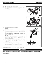
Loosen and remove screws (5) and (6).
When you remove screws (5) and (6), slow-blow fuse (7)
comes off along with electric wiring (8) and (9).
6.
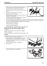
Install a new slow-blow fuse to the slow-blow fuse box
along with electric wiring (8) and (9) with screws (5) and
(6).
7.
Close covers (1), (2), and (3).
8.
Install the slow-blow fuse box to the machine.
METHOD FOR CHECKING FUNCTION OF ECSS ACCUMULATOR
For handling of the accumulator, see “HANDLE ACCUMULATOR AND GAS SPRING (2-39)”.
1.
Turn on the ECSS switch.
The function of the hydraulic spring of the accumulator reduces the bounce of the machine by absorbing
the vertical motion of the machine in travel.
2.
Compare the vertical motion of the machine when the ECSS switch is turned to ON position and OFF posi-
tion.
If there is no change in the vertical motion between the 2 settings, the accumulator gas pressure has proba-
bly dropped.
Ask your Komatsu distributor for inspection.
REMARK
The inspection must be performed with the gear speed of the 2nd to the 4th, and with the travel speed of
5 km/h or faster. ECSS (Electronically Controlled Suspension System) does not operate if the gear speed is
set to 1st or travel speed is 5 km/h or lower even if the ECSS switch is turned to ON position.
MAINTENANCE
MAINTENANCE PROCEDURE
4-35
Summary of Contents for WA480-8
Page 2: ......
Page 19: ...Distributor name Address Phone Fax Service personnel FOREWORD PRODUCT INFORMATION 1 17...
Page 29: ...LOCATION OF SAFETY LABELS SAFETY SAFETY LABELS 2 3...
Page 159: ...SWITCHES 1 ECSS switch 2 Front working lamp switch OPERATION EXPLANATION OF COMPONENTS 3 91...
Page 302: ...Securing position Fixing angle A 61 B 53 C 33 D 38 TRANSPORTATION OPERATION 3 234...
Page 324: ......
Page 397: ...Viewed from the rear side of the machine MAINTENANCE MAINTENANCE PROCEDURE 4 73...
Page 402: ......
Page 403: ...SPECIFICATIONS 5 1...
Page 406: ......
Page 422: ......
Page 423: ...REPLACEMENT PARTS 7 1...
Page 439: ......

