METHOD FOR CHECKING BRAKE DISC WEAR AMOUNT
k
k
WARNING
• When checking the condition, apply the parking brake and fix the front and rear frames by using the
frame lock bar.
• Perform this check when the brake oil temperature is 60 °C or below.
• If the disc wear approaches the wear limit, check the condition frequently, regardless of the mainte-
nance interval.
Inspection of wear on the brake disc must be done for 4 places, namely on both sides of the front and rear axle.
Perform the inspection in same procedure for all of them.
1.
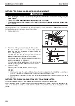
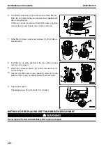
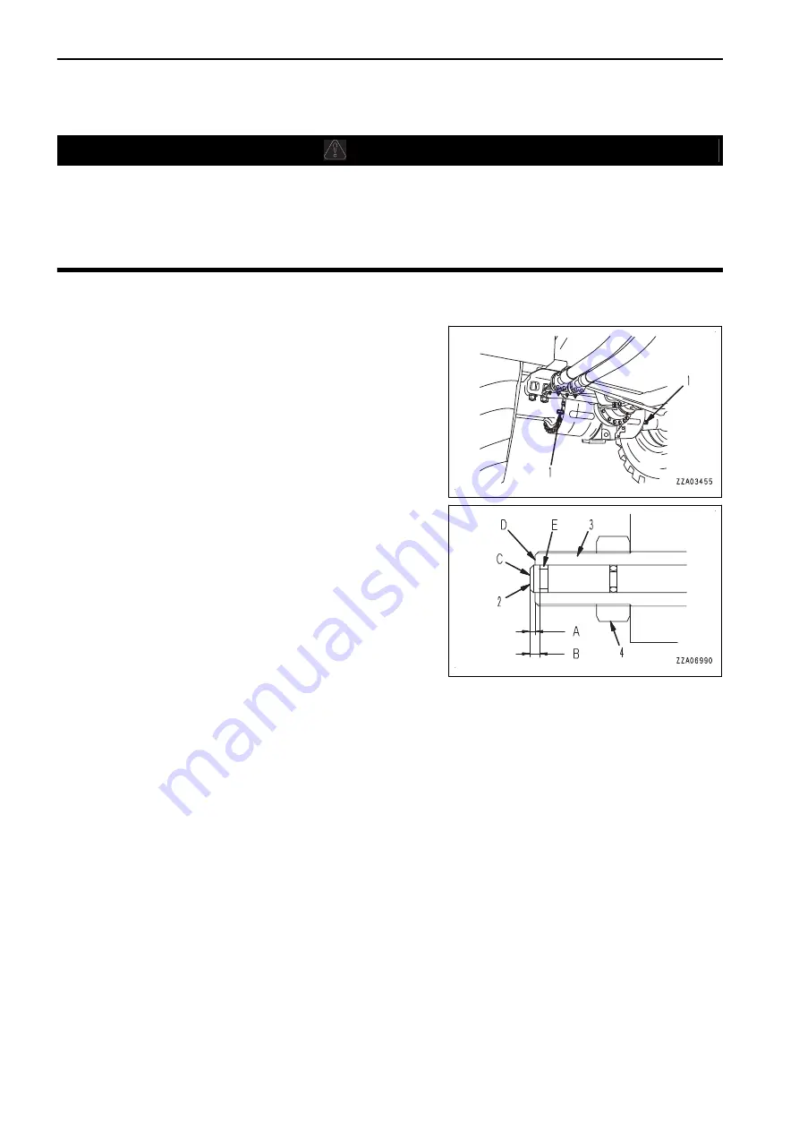
Remove cap nut (1).
2.
Push in rod (2) fully while depressing the brake pedal.
The amount of the protrusion of rod end face (C) from
guide end face (D) corresponds to wear amount (A).
Measure the protrusion.
Allowable disc wear limit (B) corresponds to the distance
between groove (E) and end face (D) of the guide.
In such case, ask your Komatsu distributor to perform in-
spection and replacement of the part.
If the disc wear approaches the wear limit, check the con-
dition frequently, regardless of the maintenance interval.
3.
Install cap nut (1).
Tightening torque: 29.4 to 39.2 Nm {3.0 to 4.0 kgm}
REMARK
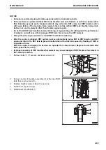
• On a new machine, the position of the end face of rod (2) is adjusted so that it matches the end face of
guide (3). Therefore, do not loosen lock nut (4) except when replacing the disc.
• Perform the operation with 2 workers. One worker depresses the brake pedal and the other pushes in
the rod.
METHOD FOR CHECKING FUNCTION OF PPC ACCUMULATOR
For handling of the accumulator, see “HANDLE ACCUMULATOR AND GAS SPRING (2-39)”.
When you cannot restart the stopped engine while the work equipment is raised, you can use, as urgent meas-
ures, the oil pressure stored in the accumulator to active the valve, thereby, lower the work equipment to the
ground.
MAINTENANCE PROCEDURE
MAINTENANCE
4-62
Summary of Contents for WA480-8
Page 2: ......
Page 19: ...Distributor name Address Phone Fax Service personnel FOREWORD PRODUCT INFORMATION 1 17...
Page 29: ...LOCATION OF SAFETY LABELS SAFETY SAFETY LABELS 2 3...
Page 159: ...SWITCHES 1 ECSS switch 2 Front working lamp switch OPERATION EXPLANATION OF COMPONENTS 3 91...
Page 302: ...Securing position Fixing angle A 61 B 53 C 33 D 38 TRANSPORTATION OPERATION 3 234...
Page 324: ......
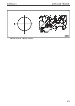
Page 397: ...Viewed from the rear side of the machine MAINTENANCE MAINTENANCE PROCEDURE 4 73...
Page 402: ......
Page 403: ...SPECIFICATIONS 5 1...
Page 406: ......
Page 422: ......
Page 423: ...REPLACEMENT PARTS 7 1...
Page 439: ......

