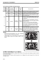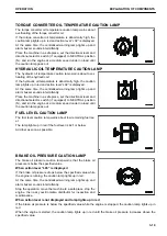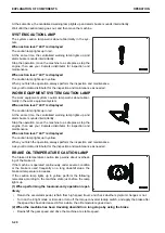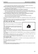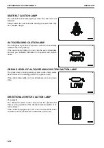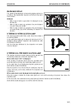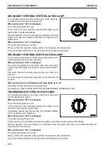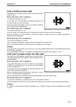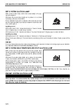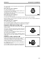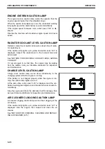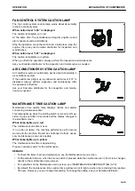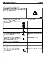
List of action level displays and required actions
De-
gree of
urgen-
cy
Action
level
Centralized
warning lamp
Buzzer
Caution
lamp
Required action
High
↑
│
│
│
│
│
↓
Low
L04
Lights up
Sounds con-
tinuously
Lights up
in red
Stop the machine immediately and ask your Komat-
su distributor for inspection and maintenance.
L03
Lights up
Sounds in-
termittently
Lights up
in red
Stop the operation and move the machine to a safe
place, then ask your Komatsu distributor for inspec-
tion and maintenance.
L02
Lights up
Sounds in-
termittently
Lights up
in red
If there is an overrun related display, reduce the en-
gine speed and machine travel speed while continu-
ing operations.
If there is an overheat related display, stop the ma-
chine at a safe place, and run the engine at medium
speed with no load.
If there is a secondary steering related display,
avoid a long time usage of the secondary steering.
If the condition is not improved, check the failure
code and ask your Komatsu distributor for inspec-
tion and maintenance.
L01
OFF
Does not
sound
Lights up
in yellow
Some functions may be restricted from use, but the
machine can operate. When you finish the opera-
tion, always have the inspection and maintenance
performed. Ask your Komatsu distributor for the in-
spection and maintenance as needed.
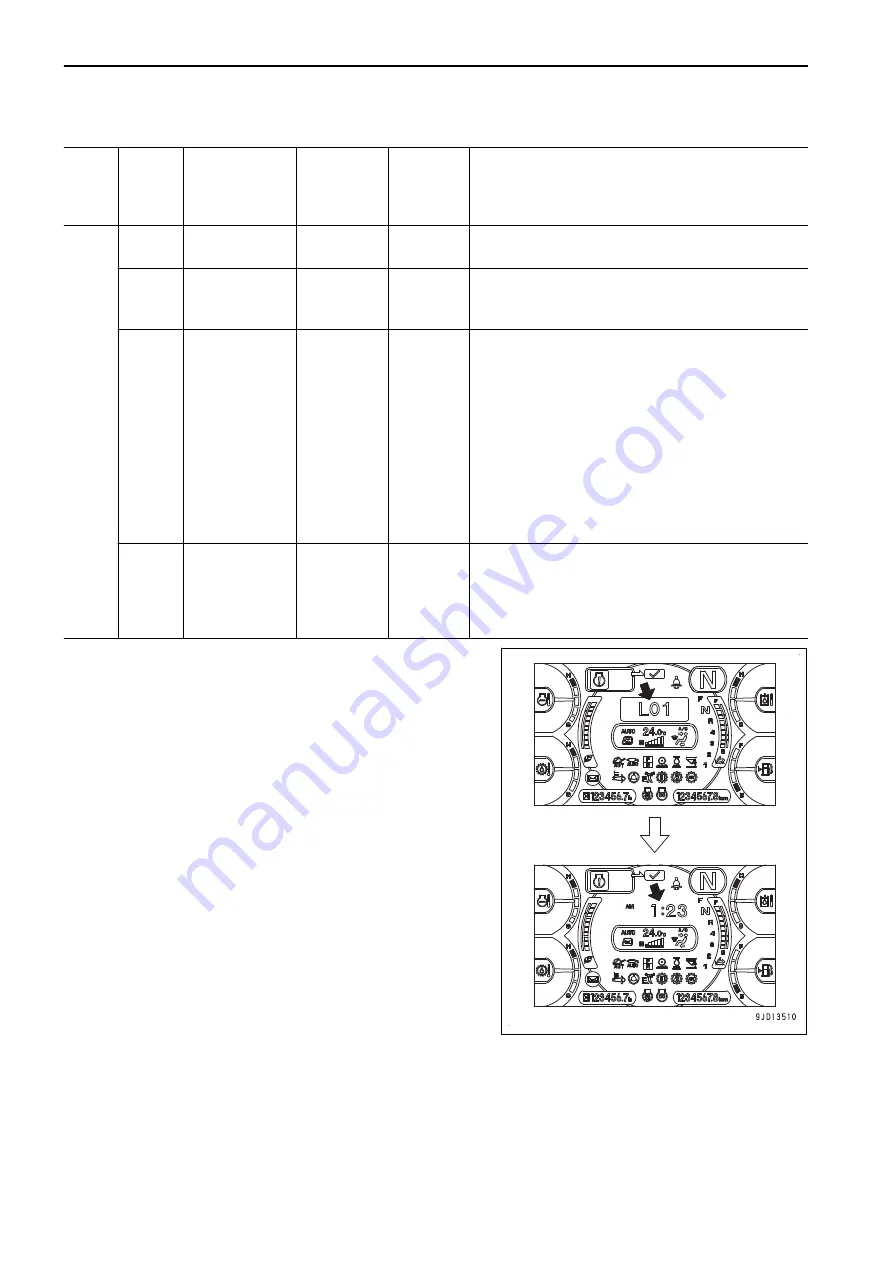
REMARK
• When the action level display is “L01”, “L01” is displayed
only for 2 seconds, and then it is turned OFF.
• If plural failures occur at the same time, the action level
with the highest urgency (the greatest number) is dis-
played.
CURRENT ABNORMALITY LIST DISPLAY
The monitor provides information on failures that occurred on the machine and necessary remedies for action
levels that are displayed.
When ENTER switch is pressed while the guidance icon is displayed, the screen changes to the “Current Ab-
normality” screen.
EXPLANATION OF COMPONENTS
OPERATION
3-16
Summary of Contents for WA480-8
Page 2: ......
Page 19: ...Distributor name Address Phone Fax Service personnel FOREWORD PRODUCT INFORMATION 1 17...
Page 29: ...LOCATION OF SAFETY LABELS SAFETY SAFETY LABELS 2 3...
Page 159: ...SWITCHES 1 ECSS switch 2 Front working lamp switch OPERATION EXPLANATION OF COMPONENTS 3 91...
Page 302: ...Securing position Fixing angle A 61 B 53 C 33 D 38 TRANSPORTATION OPERATION 3 234...
Page 324: ......
Page 397: ...Viewed from the rear side of the machine MAINTENANCE MAINTENANCE PROCEDURE 4 73...
Page 402: ......
Page 403: ...SPECIFICATIONS 5 1...
Page 406: ......
Page 422: ......
Page 423: ...REPLACEMENT PARTS 7 1...
Page 439: ......

