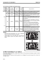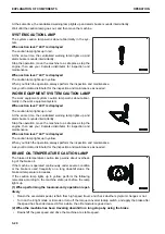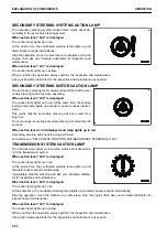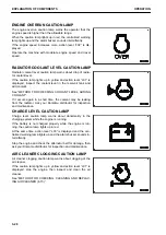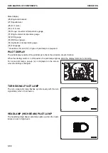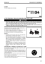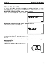
ENGINE OVERRUN CAUTION LAMP
The engine overrun caution lamp warns the operator that the
engine speed is higher than the allowable range.
When the caution lamp lights up in red, the centralized warning
lamp lights up and the alarm buzzer sounds intermittently.
If the engine speed increases more, action level “L02” is dis-
played.
Operate the machine with moderate engine speed and travel
speed.
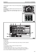
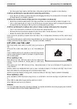
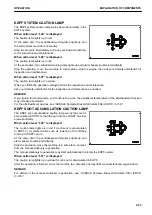
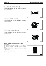
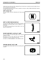
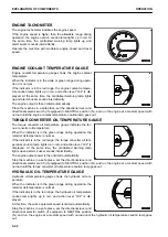
RADIATOR COOLANT LEVEL CAUTION LAMP
Radiator coolant level caution lamp warns about drop of radia-
tor coolant level.
If the caution lamp lights up in yellow and action level “L01” is
displayed, inspect the coolant level in the reservoir tank and
add coolant.
See “METHOD FOR CHECKING COOLANT LEVEL, ADDING
COOLANT”.
If it occurs again in a short time, the coolant may be leaking
from the radiator. Ask your Komatsu distributor for inspection
and maintenance.
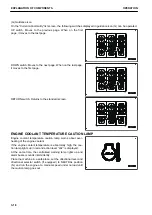
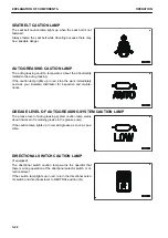
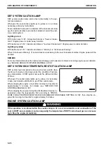
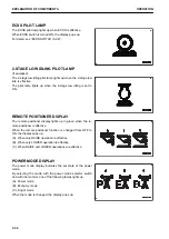
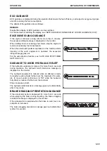
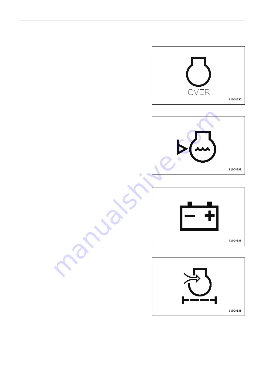
CHARGE LEVEL CAUTION LAMP
Charge level caution lamp warns about abnormality in the
charging system while the engine is running.
If the battery is not charged properly while the engine is run-
ning, the caution lamp lights up in red.
At the same time, action level “L03” is displayed and the cen-
tralized warning lamp lights up and the alarm buzzer sounds in-
termittently.
Stop the engine and check the alternator belt for damage, then
ask your Komatsu distributor for inspection and maintenance.
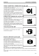
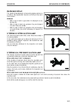
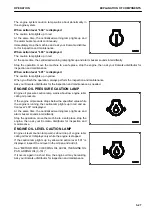
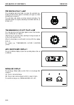
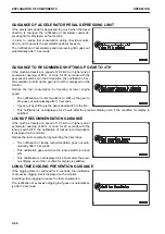
AIR CLEANER CLOGGING CAUTION LAMP
Air cleaner clogging caution lamp warns about clogging of the
air cleaner.
If the caution lamp lights up in yellow and action level “L01” is
displayed, stop the engine, then inspect and clean the air
cleaner.
See “METHOD FOR CHECKING, CLEANING AND REPLAC-
ING AIR CLEANER (4-15)”.
EXPLANATION OF COMPONENTS
OPERATION
3-28
Summary of Contents for WA480-8
Page 2: ......
Page 19: ...Distributor name Address Phone Fax Service personnel FOREWORD PRODUCT INFORMATION 1 17...
Page 29: ...LOCATION OF SAFETY LABELS SAFETY SAFETY LABELS 2 3...
Page 159: ...SWITCHES 1 ECSS switch 2 Front working lamp switch OPERATION EXPLANATION OF COMPONENTS 3 91...
Page 302: ...Securing position Fixing angle A 61 B 53 C 33 D 38 TRANSPORTATION OPERATION 3 234...
Page 324: ......
Page 397: ...Viewed from the rear side of the machine MAINTENANCE MAINTENANCE PROCEDURE 4 73...
Page 402: ......
Page 403: ...SPECIFICATIONS 5 1...
Page 406: ......
Page 422: ......
Page 423: ...REPLACEMENT PARTS 7 1...
Page 439: ......


