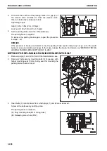
1.
Connect the clip of jumper cable (A) to the positive (+) ter-
minal of battery (C) on the failed machine.
2.
Connect the clip at the other end of jumper cable (A) to the
positive (+) terminal of battery (D) on the normal machine.
3.
Connect the clip of jumper cable (B) to the negative (-) ter-
minal of battery (D) on the normal machine.
4.
Turn the battery disconnect switch (S) of the failed ma-
chine to ON position.
5.
Connect the clip at the other end of jumper cable (B) to en-
gine block (E) of the failed machine.
METHOD FOR STARTING ENGINE
k
k
WARNING
Check both of normal machine and failed machine that the lock lever is set to LOCK position (the pilot
lamp in the switch lights up). Check also that all the control levers are in NEUTRAL position.
1.
Make sure the clips are firmly connected to the battery terminals.
2.
Start the engine of the normal machine and run it at high idle (max. speed).
3.
Turn the starting switch of the failed machine to START position and start the engine.
If the engine does not start, try it again after 2 minutes or more.
PROCEDURE FOR DISCONNECTING JUMPER CABLES
After the engine has started, disconnect the jumper cables in the reverse of the order in which they were con-
nected.
1.
Remove the clip of jumper cable (B) from engine block (E)
on the failed machine.
2.
Remove the clip of jumper cable (B) from the negative (-)
terminal of battery (D) on the normal machine.
3.
Remove the clip of jumper cable (A) from the positive (+)
terminal of battery (D) on the normal machine.
4.
Remove the clip of jumper cable (A) from the positive (+)
terminal of battery (C) on the failed machine.
OTHER TROUBLE
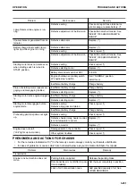
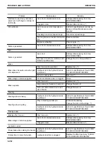
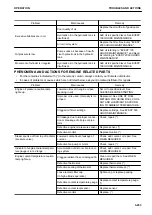
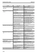
PHENOMENA AND ACTIONS FOR ELECTRICAL SYSTEM
• For the remedies indicated with (*) in the remedy column, always contact your Komatsu distributor.
• In cases of problems or causes which are not listed below, ask your Komatsu distributor for repairs.
Problem
Main causes
Remedy
Lamp does not glow brightly even
when the engine runs at high
speeds.
Defective wiring
Check and repair loose terminals,
open circuit. (*)
Defective adjustment of belt tension
Check alternator belt tension. See
"EVERY 1000 HOURS MAINTE-
NANCE".
TROUBLES AND ACTIONS
OPERATION
3-250
Summary of Contents for WA480-8
Page 2: ......
Page 19: ...Distributor name Address Phone Fax Service personnel FOREWORD PRODUCT INFORMATION 1 17...
Page 29: ...LOCATION OF SAFETY LABELS SAFETY SAFETY LABELS 2 3...
Page 159: ...SWITCHES 1 ECSS switch 2 Front working lamp switch OPERATION EXPLANATION OF COMPONENTS 3 91...
Page 302: ...Securing position Fixing angle A 61 B 53 C 33 D 38 TRANSPORTATION OPERATION 3 234...
Page 324: ......
Page 397: ...Viewed from the rear side of the machine MAINTENANCE MAINTENANCE PROCEDURE 4 73...
Page 402: ......
Page 403: ...SPECIFICATIONS 5 1...
Page 406: ......
Page 422: ......
Page 423: ...REPLACEMENT PARTS 7 1...
Page 439: ......

