METHOD FOR REPLACING HYDRAULIC OIL FILTER ELEMENT
k
k
WARNING
• Immediately after the engine is stopped, its parts and oil are still very hot and may cause burn in-
jury. Wait for the temperature to go down, and then start the work.
• When removing the oil filler cap, the oil may spout out. Turn it slowly to release the internal pres-
sure, then remove it carefully.
1.
Lower the bucket to the ground with its bottom level, apply
the parking brake, then stop the engine.
2.
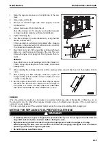
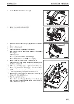
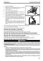
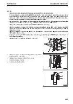
Loosen the bolts and remove cover (1).
3.
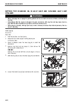
Remove mounting bolts (3) (6 pieces) of filter cover (2) on
the top of the tank, then remove the cover.
The cover may be jumped out by spring (4).
While pressing down the cover, remove the bolts.
4.
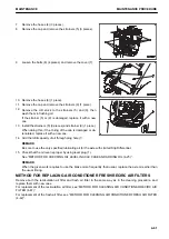
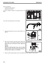
Remove spring (4) and bypass valve (5), then pull out ele-
ment (6).
5.
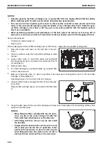
Check inside of the tank for foreign material, then clean it.
6.
Install new element (6), then set bypass valve (5), spring
(4), and cover (2) to the tank.
If the O-ring of the cover is damaged or deteriorated, re-
place it.
7.
While pressing down the cover, tighten the mounting bolts
evenly.
8.
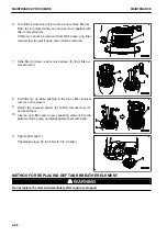
Check the hydraulic oil level oil level.
Check that the hydraulic oil is at the specified level. For
details, see “METHOD FOR CHECKING OIL LEVEL IN
HYDRAULIC TANK, ADDING OIL (4-42)”.
9.
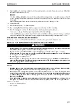
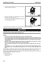
Run the engine at low idle, and extend and retract each of
the steering, bucket, and boom cylinders 4 to 5 times, tak-
ing care not to move them to the stroke end (stop them approximately 100 mm before the stroke end).
NOTICE
If the engine is run at high speed immediately after startup or a cylinder is pushed up to its stroke
end, air taken inside the cylinder may cause damage to the piston packing.
MAINTENANCE PROCEDURE
MAINTENANCE
4-58
Summary of Contents for WA480-8
Page 2: ......
Page 19: ...Distributor name Address Phone Fax Service personnel FOREWORD PRODUCT INFORMATION 1 17...
Page 29: ...LOCATION OF SAFETY LABELS SAFETY SAFETY LABELS 2 3...
Page 159: ...SWITCHES 1 ECSS switch 2 Front working lamp switch OPERATION EXPLANATION OF COMPONENTS 3 91...
Page 302: ...Securing position Fixing angle A 61 B 53 C 33 D 38 TRANSPORTATION OPERATION 3 234...
Page 324: ......
Page 397: ...Viewed from the rear side of the machine MAINTENANCE MAINTENANCE PROCEDURE 4 73...
Page 402: ......
Page 403: ...SPECIFICATIONS 5 1...
Page 406: ......
Page 422: ......
Page 423: ...REPLACEMENT PARTS 7 1...
Page 439: ......


