6.4 Central lubrication system
Attachments, Options
6-46
WA500-6H – VEAM430100
6.4
Central lubrication system
6.4.1
Operating the central lubrication system
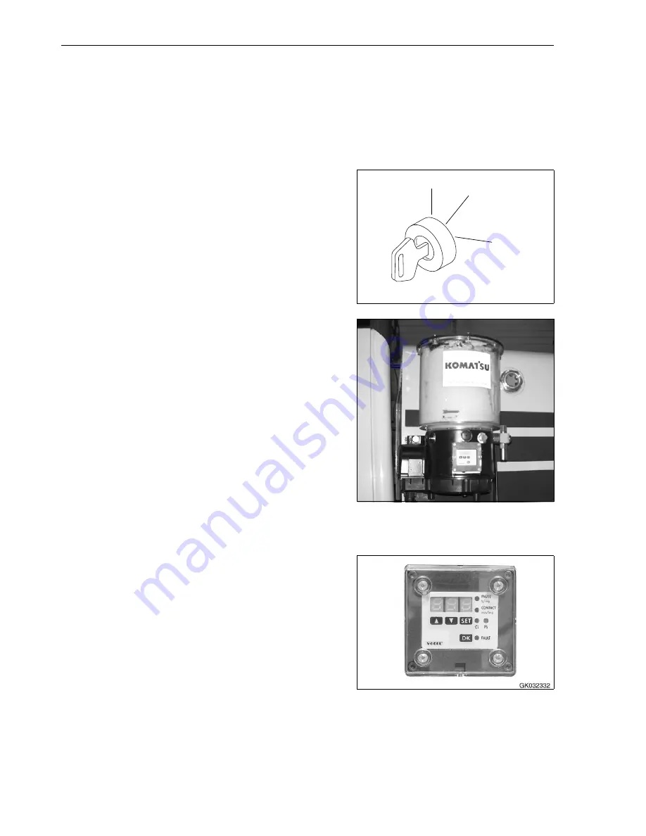
The pump with the grease container is located at the left of the
engine bonnet, above the fender.
1. Turn the ignition switch to ON position (B).
This switches on the grease pump.
2. Watch the grease container.
If the mixer blades are turning inside the grease container,
the lubrication system is OK.
If the mixer blades are not turning, no automatic lubrication
is taking place.
To eliminate the malfunction, contact your KOMATSU dealer.
6.4.2
Display and control unit
The display and control unit is protected by a transparent plastic
cover against splashing water and mechanical damage. For pro-
gramming, the cover has to be dismounted and, following pro-
gramming, reattached with a screwdriver.
GK050049
A
B
C
GK050311
Summary of Contents for WA500-6H
Page 2: ......
Page 3: ...Foreword WA500 6H VEAM430100 1 1 1 Foreword...
Page 26: ...1 7 CE Conforming equipment Foreword 1 24 WA500 6H VEAM430100...
Page 254: ...3 7 Troubleshooting Operation 3 188 WA500 6H VEAM430100...
Page 344: ...4 9 Service procedure Every 12000 hours service Maintenance 4 90 WA500 6H VEAM430100...
Page 345: ...Technical Data WA500 6H VEAM430100 5 1 5 Technical Data...
Page 347: ...Technical Data 5 1 Technical data WA500 6H VEAM430100 5 3 GK032301 A B H I G C E F D...
Page 352: ...5 4 Limit values for slopes Technical Data 5 8 WA500 6H VEAM430100...
Page 401: ...Index WA500 6H VEAM430100 7 1 7 Index...
Page 407: ...Notes WA500 6H VEAM430100 8 1 8 Notes...
Page 408: ...Notes 8 2 WA500 6H VEAM430100...
Page 409: ...Notes WA500 6H VEAM430100 8 3...
Page 410: ...Notes 8 4 WA500 6H VEAM430100...
Page 411: ...Notes WA500 6H VEAM430100 8 5...
Page 412: ...Notes 8 6 WA500 6H VEAM430100...


