Troubleshooting
4.1 Towing the machine
WA70-7 – VENAM02003
4-3
2. Tip up the operator's cab.
For details see 5.1.1 “Tipping up the operator's cab” (5-3).
3. Remove the protective caps from the valves.
NOTICE
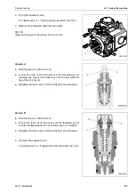
Observe the types of the valves: Version A or B
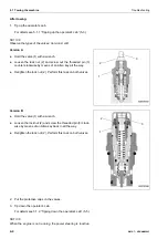
Version A
Hold the valve (1) with a wrench.
Loosen the lock nut (2) and screw in the threaded pin (3)
clockwise by means of an Allen key until it is level with the
top of the lock nut (4).
Retighten the lock nut (2). Perform this task on both valves.
Version B
Hold the valve (1) with a wrench.
Loosen the lock nut (2) and screw out the threaded pin (3)
counter-clockwise by means of an Allen key by 2 rotations.
Retighten the lock nut (2). Perform this task on both valves.
4. Tip down the operator's cab.
For details see 5.1.2 “Tipping down the operator's cab” (5-5).
G0070307
1
3
1
2
1
3
2
Summary of Contents for WA70-7
Page 2: ......
Page 3: ...Foreword WA70 7 VENAM02003 1 1 1 Foreword...
Page 23: ...Foreword 1 5 Table of contents WA70 7 VENAM02003 1 21 Blank for technical reason...
Page 28: ...1 7 Equipment Foreword 1 26 WA70 7 VENAM02003...
Page 75: ...Operation WA70 7 VENAM02003 3 1 3 Operation...
Page 114: ...3 2 Descriptions of the individual elements Operation 3 40 WA70 7 VENAM02003 Fuse allocation...
Page 185: ...Troubleshooting WA70 7 VENAM02003 4 1 4 Troubleshooting...
Page 203: ...Maintenance WA70 7 VENAM02003 5 1 5 Maintenance...
Page 277: ...Technical data WA70 7 VENAM02003 6 1 6 Technical data...
Page 283: ...Special equipment attachments WA70 7 VENAM02003 7 1 7 Special equipment attachments...
Page 291: ...Index WA70 7 VENAM02003 8 1 8 Index...
Page 296: ...8 1 Index Index 8 6 WA70 7 VENAM02003...
Page 297: ...Notes WA70 7 VENAM02003 9 1 9 Notes...
Page 298: ...Notes 9 2 WA70 7 VENAM02003...
Page 299: ...Notes WA70 7 VENAM02003 9 3...
Page 300: ...Notes 9 4 WA70 7 VENAM02003...
Page 301: ...Notes WA70 7 VENAM02003 9 5...
Page 302: ...Notes 9 6 WA70 7 VENAM02003...


