5.8 Maintenance procedure
Maintenance every 50 service hours
Maintenance
5-44
WA70-7 – VENAM02003
Check central lubrication system, add grease
The following maintenance work is to be carried out as required
or every 50 service hours:
General function check
The basic function of the pilot device and the system compo-
nents can be checked by activating intermediate lubrication.
Regular check of the system components for leakage and
damage.
Visual inspection of the state of lubrication of the bearings
and observation of the lubrication pattern.
In the event of fault indications, consult your Komatsu distributor
to rectify the fault.
NOTICE
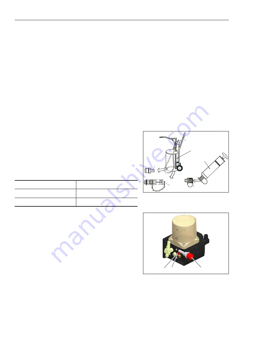
Only refill using clean lubricant and a suitable filling device (A or
B). Contaminated lubricant can lead to serious system malfunc-
tions.
Permitted lubricants
Grease of NLGI class 2 with EP additives, compatible with plas-
tics, NBR elastomers, copper and copper alloys and a max. flow
pressure of 700 mbar.
Fill the lubricant container to above the “MIN” marking but no
higher than the “MAX” marking.
When using the factory setting, it is sufficient to fill up for a mini-
mum of 50 hours.
If the lubrication times have been changed or several intermedi-
ate lubrications have been carried out, the level check must be
brought forward.
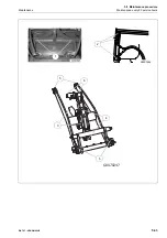
Depending on the design, lubricant can only be added via:
1. Cone-shaped grease nipple
2. Filling attachment
3. Filling cylinder
The connecting pieces must be free from dirt.
The transparent lubricant container allows you to carry out a vis-
ual level check.
If the container has been emptied to below the “MIN” mark, the
entire system must be bled. Consult your Komatsu distributor to
have the system bled.
1
1, 2
2
3
M20X1,5
A
B
Temperature range of grease
Viscosity classes
-20 °C to 120 °C
G2 LI
-40 °C to 100 °C
GLT2 LI
1 3
2
Summary of Contents for WA70-7
Page 2: ......
Page 3: ...Foreword WA70 7 VENAM02003 1 1 1 Foreword...
Page 23: ...Foreword 1 5 Table of contents WA70 7 VENAM02003 1 21 Blank for technical reason...
Page 28: ...1 7 Equipment Foreword 1 26 WA70 7 VENAM02003...
Page 75: ...Operation WA70 7 VENAM02003 3 1 3 Operation...
Page 114: ...3 2 Descriptions of the individual elements Operation 3 40 WA70 7 VENAM02003 Fuse allocation...
Page 185: ...Troubleshooting WA70 7 VENAM02003 4 1 4 Troubleshooting...
Page 203: ...Maintenance WA70 7 VENAM02003 5 1 5 Maintenance...
Page 277: ...Technical data WA70 7 VENAM02003 6 1 6 Technical data...
Page 283: ...Special equipment attachments WA70 7 VENAM02003 7 1 7 Special equipment attachments...
Page 291: ...Index WA70 7 VENAM02003 8 1 8 Index...
Page 296: ...8 1 Index Index 8 6 WA70 7 VENAM02003...
Page 297: ...Notes WA70 7 VENAM02003 9 1 9 Notes...
Page 298: ...Notes 9 2 WA70 7 VENAM02003...
Page 299: ...Notes WA70 7 VENAM02003 9 3...
Page 300: ...Notes 9 4 WA70 7 VENAM02003...
Page 301: ...Notes WA70 7 VENAM02003 9 5...
Page 302: ...Notes 9 6 WA70 7 VENAM02003...

