Foreword
1.2 Safety information
WA70-7 – VENAM02003
1-7
1.2.2
Safety labels
Safety labels are affixed to the machine to inform the operating
or maintenance personnel immediately of hazards in the opera-
tion or maintenance of the machine.
For details see “Safety labels (2-2)”.
Safety labels using pictograms
Safety pictograms use a picture to express a hazard level that
corresponds to the signal word. The pictures used are intended
to help the operating and maintenance personnel understand
the level and type of hazard at all times. Safety pictograms show
the type of hazardous condition at the top or on the left side, and
the method of avoiding the hazardous condition at the bottom or
on the right side. In addition, the type of hazardous condition is
displayed inside a triangle, and the method of avoiding the haz-
ardous condition is shown inside a circle.
Komatsu cannot predict every circumstance that might involve a
potential hazard in operation and maintenance. Therefore, the
safety messages in this manual and on the machine may not
include all possible safety precautions.
If any procedures or actions not specifically recommended or
allowed in this manual are used, it is your responsibility to take
the necessary steps to ensure safety.
Never perform any type of work or use the machine in any way
that is expressly prohibited in this manual.
The explanations, values, and illustrations in this manual were
prepared based on the latest information available at the time.
Continuous improvements to the machine's design may result in
minor changes to the machine that may not be reflected in this
manual. Consult Komatsu or your Komatsu distributor for the lat-
est information available on your machine or for questions
regarding the information in this manual.
GK032002
Part no.
Summary of Contents for WA70-7
Page 2: ......
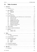
Page 3: ...Foreword WA70 7 VENAM02003 1 1 1 Foreword...
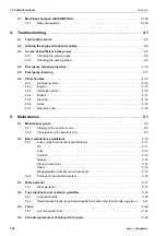
Page 23: ...Foreword 1 5 Table of contents WA70 7 VENAM02003 1 21 Blank for technical reason...
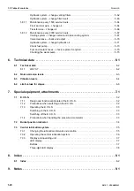
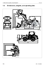
Page 28: ...1 7 Equipment Foreword 1 26 WA70 7 VENAM02003...
Page 75: ...Operation WA70 7 VENAM02003 3 1 3 Operation...
Page 114: ...3 2 Descriptions of the individual elements Operation 3 40 WA70 7 VENAM02003 Fuse allocation...
Page 185: ...Troubleshooting WA70 7 VENAM02003 4 1 4 Troubleshooting...
Page 203: ...Maintenance WA70 7 VENAM02003 5 1 5 Maintenance...
Page 277: ...Technical data WA70 7 VENAM02003 6 1 6 Technical data...
Page 283: ...Special equipment attachments WA70 7 VENAM02003 7 1 7 Special equipment attachments...
Page 291: ...Index WA70 7 VENAM02003 8 1 8 Index...
Page 296: ...8 1 Index Index 8 6 WA70 7 VENAM02003...
Page 297: ...Notes WA70 7 VENAM02003 9 1 9 Notes...
Page 298: ...Notes 9 2 WA70 7 VENAM02003...
Page 299: ...Notes WA70 7 VENAM02003 9 3...
Page 300: ...Notes 9 4 WA70 7 VENAM02003...
Page 301: ...Notes WA70 7 VENAM02003 9 5...
Page 302: ...Notes 9 6 WA70 7 VENAM02003...


