7.3 Central lubrication system
Special equipment, attachments
7-8
WA70-7 – VENAM02003
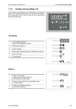
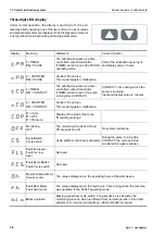
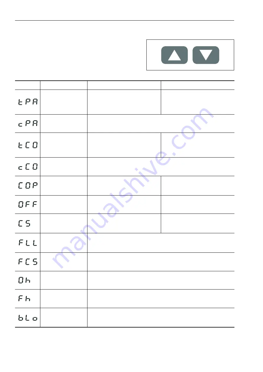
Three-digit LED display
Under normal operation, the display is switched off. It is acti-
vated by briefly pressing one of the two buttons. Current values
and preset parameters are displayed. The display also serves as
a user guide when programming operating parameters.
Display
Meaning
Statement
Control function
t
= TIMER
PA
= PAUSE
The pilot device works as a time-
controlled contact transmitter
(TIMER) and is found in the PAUSE
operating mode.
Part of the lubrication cycle input
and display value in hours
c
= COUNTER
PA
= PAUSE
Caution! Do not use
This mode triggers a malfunction
t
= TIMER
CO
= CONTACT
The pilot device works as a time-
controlled contact transmitter
(TIMER) and is found in the pump
running time (CONTACT).
CONTACT = time during which the
pump is pumping
Input and display value in minutes
c
= COUNTER
CO
= CONTACT
Caution! Do not use
This mode triggers a malfunction
C
= Cycle
O
= OFF
P
= Pressure
Display of the start of the menu
“Monitoring settings”
Monitoring
OFF
The monitoring functions CS and
PS are switched off.
No system monitoring
C
ycle
S
witch
Cycle switch
Cycle switch monitoring is activated
During the pump running time
CONTACT, the cycle switch is
monitored for signal emission.
F
ault
L
ow
L
evel
Fault: too low
level
Not used
F
ault
C
ycle
S
witch
Fault: Cycle switch
Not used
O
peration
H
our Meter
Service meter
The values displayed are the operating hours of the pilot device.
F
ault
H
our Meter
Fault hour meter
The values displayed are the fault hours. Time during which the machine
was operated in the FAULT operating mode.
B
lock operation
Missing signal from cycle switch. The pilot device is still within the
monitoring process, which is different from normal operation. If the fault
persists over 3 pump running times, a fault indication is issued.
Summary of Contents for WA70-7
Page 2: ......
Page 3: ...Foreword WA70 7 VENAM02003 1 1 1 Foreword...
Page 23: ...Foreword 1 5 Table of contents WA70 7 VENAM02003 1 21 Blank for technical reason...
Page 28: ...1 7 Equipment Foreword 1 26 WA70 7 VENAM02003...
Page 75: ...Operation WA70 7 VENAM02003 3 1 3 Operation...
Page 114: ...3 2 Descriptions of the individual elements Operation 3 40 WA70 7 VENAM02003 Fuse allocation...
Page 185: ...Troubleshooting WA70 7 VENAM02003 4 1 4 Troubleshooting...
Page 203: ...Maintenance WA70 7 VENAM02003 5 1 5 Maintenance...
Page 277: ...Technical data WA70 7 VENAM02003 6 1 6 Technical data...
Page 283: ...Special equipment attachments WA70 7 VENAM02003 7 1 7 Special equipment attachments...
Page 291: ...Index WA70 7 VENAM02003 8 1 8 Index...
Page 296: ...8 1 Index Index 8 6 WA70 7 VENAM02003...
Page 297: ...Notes WA70 7 VENAM02003 9 1 9 Notes...
Page 298: ...Notes 9 2 WA70 7 VENAM02003...
Page 299: ...Notes WA70 7 VENAM02003 9 3...
Page 300: ...Notes 9 4 WA70 7 VENAM02003...
Page 301: ...Notes WA70 7 VENAM02003 9 5...
Page 302: ...Notes 9 6 WA70 7 VENAM02003...


