EXPLANATION OF COMPONENTS
OPERATION
3-60
AIR CONDITIONER
3
(If equipped)
GENERAL LOCATIONS AND FUNCTION OF CONTROL PANEL
3
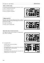
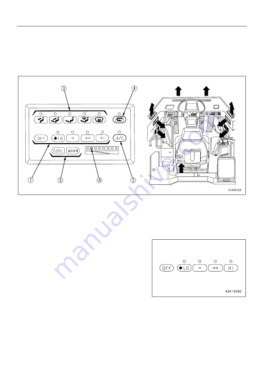
FAN SWITCH
This switch (1) can be used to adjust the airflow in four stages.
It also acts as the main switch for the air conditioner. When the
OFF switch is pressed, the fan stops.
When the switch is pressed, the indicator lamp above the
switch lights up to display the airflow.
(1)
Fan switch
(4)
FRESH/RECIRC selector switch
(2)
Air conditioner switch
(5)
Temperature control switch
(3)
Mode selector switch
(A)
Temperature level indicator lamp
Summary of Contents for WA800-3E0
Page 2: ......
Page 3: ...FOREWORD 11...
Page 27: ...SAFETY SAFETY LABELS 2 5 LOCATION OF SAFETY LABELS 2...
Page 66: ...GENERAL VIEW OPERATION 3 4...
Page 84: ...EXPLANATION OF COMPONENTS OPERATION 3 22 SWITCHES 3...
Page 224: ...TROUBLESHOOTING OPERATION 3 162...
Page 309: ...SPECIFICATIONS 15...
Page 330: ...HANDLING MACHINES EQUIPPED WITH VHMS ATTACHMENTS OPTIONS 6 20...
Page 331: ...INDEX 17...
Page 332: ...INDEX 7 2...
Page 335: ...COLOPHON 18...

