OPERATION
OPERATION
3-102
2.
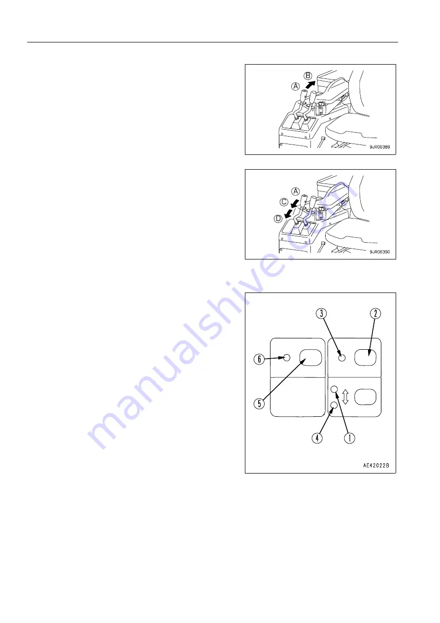
When the remote positioner RAISE stop display lamp (2) is
lighted up, if the lift arm control lever is moved from HOLD
position (A) to RAISE position (B), the lever will stay in that
position.
When the lift arm rises to the RAISE stop set position, it will
reduce speed and stop, and at the same time, the lift arm
control lever will return to HOLD position (A).
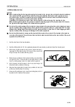
3.
When remote positioner LOWER stop display lamp (3) is
lighted up, if the lift arm control lever is moved from HOLD
position (A) to FLOAT position (C) or maximum LOWER
position (D), and the lift arm goes down to the LOWER stop
set position, it reduces speed and stops. If the lever is held
in position, the lift arm is set to the STOP condition.
METHOD OF SETTING REMOTE POSITIONER STOP POSITION
1.
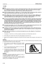
When remote positioner RAISE stop display lamp (1) is
lighted up, operate the lift arm control lever to raise the lift
arm to the desired height (a position above horizontal).
Then return the lift arm control lever to the HOLD position
and press remote positioner RAISE position set switch (2).
Remote positioner RAISE stop display lamp (1) will go out,
and remote positioner RAISE set pilot lamp (3) will flash for
2.5 seconds.
When remote positioner RAISE set pilot lamp (3) goes out
and remote positioner RAISE stop display lamp (1) also
goes out, the RAISE stop position is saved to memory and
the setting operation is completed.
2.
When remote positioner LOWER stop display lamp (4) is
lighted up, operate the lift arm control lever to lower the lift
arm to the desired height (a position below horizontal).
Then return the lift arm control lever to the HOLD position
and press remote positioner LOWER position set switch
(5).
Remote positioner LOWER stop display lamp (4) will go
out, and remote positioner LOWER set pilot lamp (6) will
flash for 2.5 seconds.
When remote positioner LOWER set pilot lamp (6) goes
out and remote positioner LOWER stop display lamp (4)
also goes out, the LOWER stop position is saved to mem-
ory and the setting operation is completed.
Summary of Contents for WA800-3E0
Page 2: ......
Page 3: ...FOREWORD 11...
Page 27: ...SAFETY SAFETY LABELS 2 5 LOCATION OF SAFETY LABELS 2...
Page 66: ...GENERAL VIEW OPERATION 3 4...
Page 84: ...EXPLANATION OF COMPONENTS OPERATION 3 22 SWITCHES 3...
Page 224: ...TROUBLESHOOTING OPERATION 3 162...
Page 309: ...SPECIFICATIONS 15...
Page 330: ...HANDLING MACHINES EQUIPPED WITH VHMS ATTACHMENTS OPTIONS 6 20...
Page 331: ...INDEX 17...
Page 332: ...INDEX 7 2...
Page 335: ...COLOPHON 18...


