OPERATION
OPERATION
3-124
ADJUSTING WORK EQUIPMENT POSTURE
3
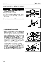
WARNING
q
Stop the machine on level ground and put blocks in
front of and behind the tires.
q
Turn the parking brake switch ON.
q
Lock the front and rear frames with the frame lock bar.
q
Always hang a warning tag on the work equipment
control levers.
q
Do not go under the work equipment when the arm is
raised.
ADJUSTING BUCKET POSITIONER
3
1.
Lower the bucket to the ground, set it to the desired digging
angle, return the bucket control lever to the HOLD position,
set the work equipment lock lever to the LOCK position,
then stop the engine.
2.
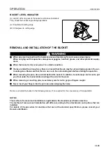
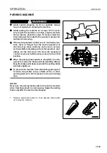
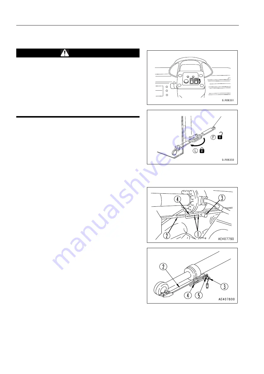
Loosen two bolts (1) and adjust mounting bracket (4) of the
proximity switch so that the rear tip of angle (2) is in line
with the center of the sensing surface of proximity switch
(3). Then tighten the bolts to hold the bracket in position.
3.
Loosen two nuts (5) and adjust to make a clearance of 3 to
5 mm between bar (2) and the sensing surface of proximity
switch (3). Then tighten the nuts to hold in position.
Tightening torque: 14.75 to 19.65 Nm (1.5 to 2.0 kgm)
4.
After adjusting, start the engine and raise the lift arm.
Operate the bucket control lever to the DUMP position,
then operate it to the TILT BACK position and check that
the lever is automatically returned to the HOLD position
when the bucket reaches the desired digging angle.
Summary of Contents for WA800-3E0
Page 2: ......
Page 3: ...FOREWORD 11...
Page 27: ...SAFETY SAFETY LABELS 2 5 LOCATION OF SAFETY LABELS 2...
Page 66: ...GENERAL VIEW OPERATION 3 4...
Page 84: ...EXPLANATION OF COMPONENTS OPERATION 3 22 SWITCHES 3...
Page 224: ...TROUBLESHOOTING OPERATION 3 162...
Page 309: ...SPECIFICATIONS 15...
Page 330: ...HANDLING MACHINES EQUIPPED WITH VHMS ATTACHMENTS OPTIONS 6 20...
Page 331: ...INDEX 17...
Page 332: ...INDEX 7 2...
Page 335: ...COLOPHON 18...


