OPERATION
EXPLANATION OF COMPONENTS
3-65
HANDLING WIRELESS
3
NOTICE
The engine service monitor is installed under the lunchbox, so do not place any wireless device on top of
the lunchbox.
METHOD OF INSTALLING WIRELESS
3
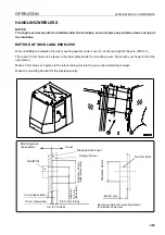
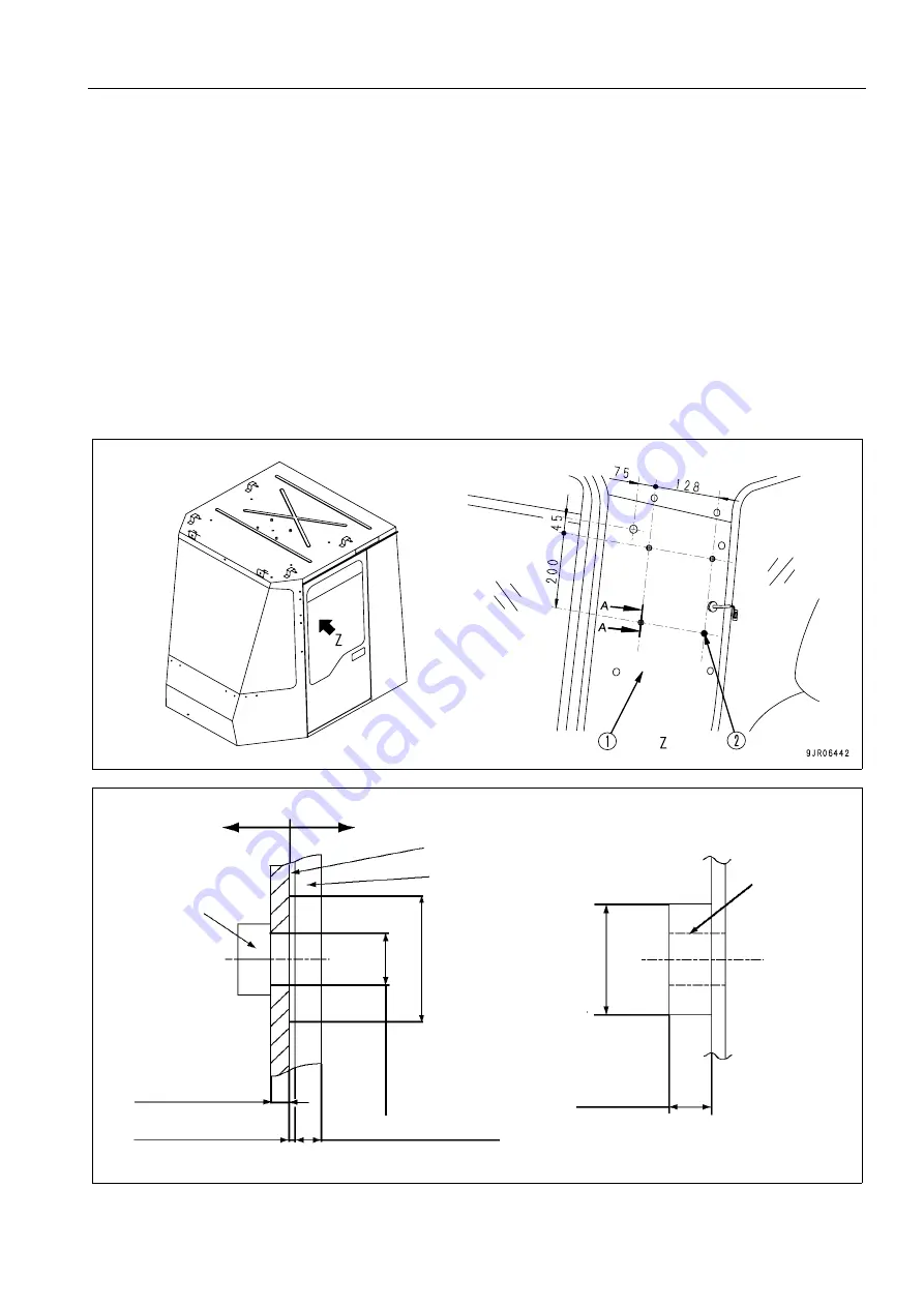
When installing the wireless, there is mounting seat (2) under cover (1) at the rear right of the cab. (M10 x 4)
There are 30 mm holes at 4 places in the steel plate inside the mounting cover. Press with your finger to find the
open place.
Make 30 mm holes at 4 places in the interior lining stuck to the cover, then install the wireless.
Make the mounting bracket for the wireless locally.
Cover
Mounting seat
(base plate)
Nut (M10)
Steel plate for cover
Lining of cover
12.2 mm Drill
Diameter:
26 mm
Min: 8 mm
6.5 mm (Lining)
Diameter:
12.5 mm
(B
as
e pl
a
te
)
Diameter : 30
mm
(S
teel
p
late
portion
)
4.5 mm (Base plate)
1.2 mm (Steel plate)
A -A (4 PLACES)
Recommendation for mounting bracket
for wireless equipment
Summary of Contents for WA800-3E0
Page 2: ......
Page 3: ...FOREWORD 11...
Page 27: ...SAFETY SAFETY LABELS 2 5 LOCATION OF SAFETY LABELS 2...
Page 66: ...GENERAL VIEW OPERATION 3 4...
Page 84: ...EXPLANATION OF COMPONENTS OPERATION 3 22 SWITCHES 3...
Page 224: ...TROUBLESHOOTING OPERATION 3 162...
Page 309: ...SPECIFICATIONS 15...
Page 330: ...HANDLING MACHINES EQUIPPED WITH VHMS ATTACHMENTS OPTIONS 6 20...
Page 331: ...INDEX 17...
Page 332: ...INDEX 7 2...
Page 335: ...COLOPHON 18...

