OPERATION
OPERATION
3-125
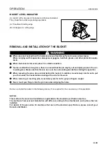
BUCKET LEVEL INDICATOR
3
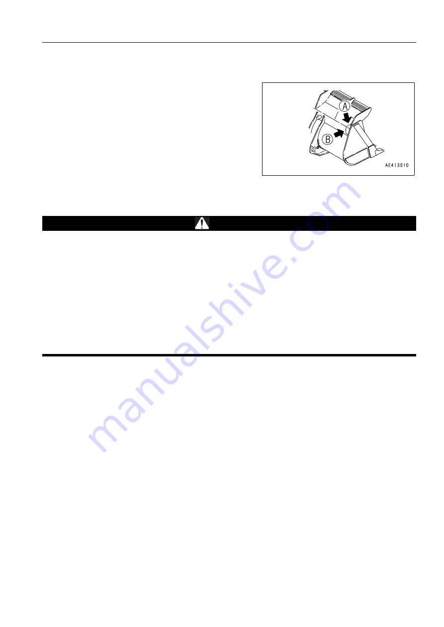
(A) and (B) at the top rear of the bucket are the level indicators.
They check the bucket angle during operations.
(A): Parallel with cutting edge
(B): 90 degrees to cutting edge
REMOVAL AND INSTALLATION OF THE BUCKET
3
WARNING
q
When pins are knocked in with a hammer, pieces of metal may fly and cause serious injury.
When carrying out this operation, always wear goggles, hard hat, gloves, and other protective equip-
ment.
q
When the bucket is removed, place it in a stable condition.
q
If pins are hit with a strong force, there is a hazard that the pin may fly out and injure people in the sur-
rounding area. Make sure that there is no one in the surrounding area before starting the operation.
q
When removing the pins, do not stand behind the bucket. In addition, be extremely careful not to put
your foot under the bucket while standing at the side for the work.
q
When removing or inserting pins, be extremely careful not to get your fingers caught.
q
Never insert your fingers into the pin holes when aligning the holes.
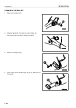
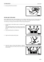
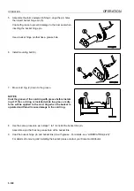
Remove or install the bucket in the following manner, if so required for the convenience of transportation.
NOTICE
This method of removal and installation is applicable to the standard specification machine.
The method of removal and installation will differ according to the attachments and options that are
installed.
For details of the procedure for machines that are not the standard specification, please consult your
Komatsu distributor.
Summary of Contents for WA800-3E0
Page 2: ......
Page 3: ...FOREWORD 11...
Page 27: ...SAFETY SAFETY LABELS 2 5 LOCATION OF SAFETY LABELS 2...
Page 66: ...GENERAL VIEW OPERATION 3 4...
Page 84: ...EXPLANATION OF COMPONENTS OPERATION 3 22 SWITCHES 3...
Page 224: ...TROUBLESHOOTING OPERATION 3 162...
Page 309: ...SPECIFICATIONS 15...
Page 330: ...HANDLING MACHINES EQUIPPED WITH VHMS ATTACHMENTS OPTIONS 6 20...
Page 331: ...INDEX 17...
Page 332: ...INDEX 7 2...
Page 335: ...COLOPHON 18...


