

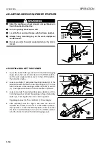
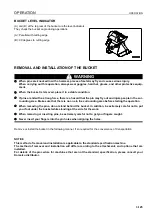
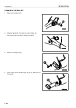
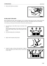


OPERATION
OPERATION
3-132
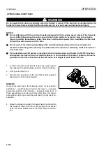
HANDLING THE TIRES
3
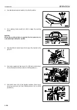
PRECAUTIONS WHEN HANDLING TIRES
3
CAUTION
If a tire has reached any of the following service limits,
there is danger that the tire may burst or cause an acci-
dent, so to ensure safety, replace it with a new tire.
Service limits for wear
When the remaining depth of the grooves on construction
equipment tires (at a point approx. 1/4 of the tread width) is
15% of the groove depth on a new tire.
When the tire shows marked uneven wear, stepped wear
or other abnormal wear, or when the cord layer is exposed.
Service limits for damage
When there is external damage extending to the cord or
when the cord is broken
When the cord is cut or there is dragging
When the tire is peeling (there is separation)
When the bead is damaged
For tubeless tires, when there is air leakage or improper
repair
Please contact your Komatsu distributor when replacing the
tires. It is dangerous to jack up the machine without taking due
care.
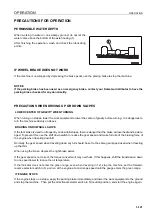
TIRE PRESSURE
3
Measure the tire pressure before starting operations, when the tires are cool.
If the tire inflation pressure is too low, there will be overload; if it is too high, it will cause tire cuts and shock burst.
To prevent these problems, adjust the tire inflation pressure according to the table on the next page.
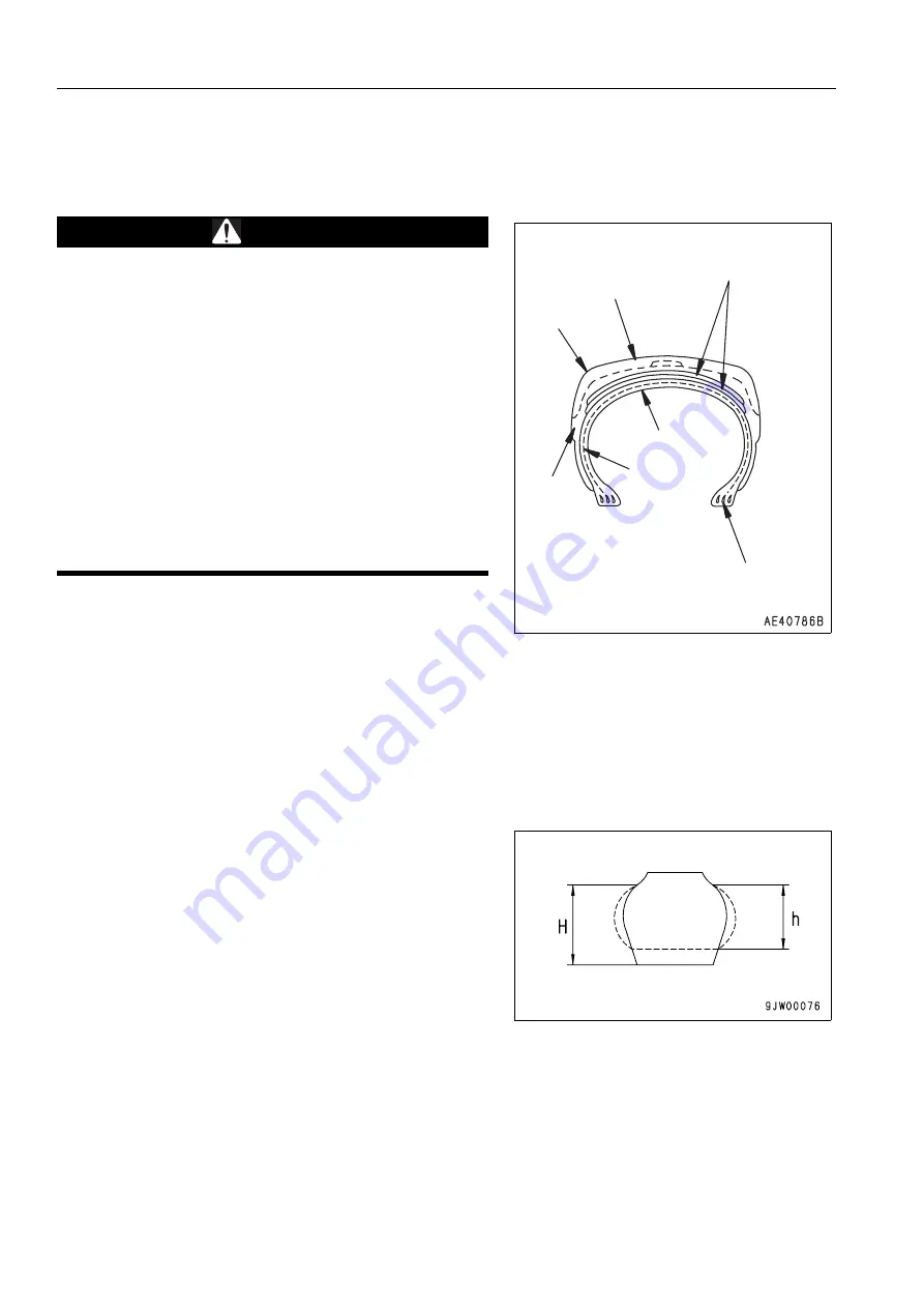
Deflection ratio = H - h / H x 100
As a guideline that can be checked visibly, the deflection ratio of the front tire (deflection/free height) is as follows.
When carrying normal load (lift arm horizontal): Approx. 10 to 15 %
When digging (rear wheels off ground): Approx. 20 to 25 %
When checking the tire inflation pressure, check also for small scratches or peeling of the tire, for nails or pieces of
metal which may cause punctures, and for any abnormal wear.
Clearing fallen stones and rocks from the operating area and maintaining the surface will extend the tire life and
give improved economy.
Breaker or belt
(cord layer)
Tread
Shoulder
Side wall
Inner liner
Carcass
Bead
Summary of Contents for WA800-3E0
Page 2: ......
Page 3: ...FOREWORD 11...
Page 27: ...SAFETY SAFETY LABELS 2 5 LOCATION OF SAFETY LABELS 2...
Page 66: ...GENERAL VIEW OPERATION 3 4...
Page 84: ...EXPLANATION OF COMPONENTS OPERATION 3 22 SWITCHES 3...
Page 224: ...TROUBLESHOOTING OPERATION 3 162...
Page 309: ...SPECIFICATIONS 15...
Page 330: ...HANDLING MACHINES EQUIPPED WITH VHMS ATTACHMENTS OPTIONS 6 20...
Page 331: ...INDEX 17...
Page 332: ...INDEX 7 2...
Page 335: ...COLOPHON 18...


