UAB AMALVA we reserve the right to make changes without prior notice
25
C3-16-01-v1
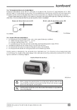
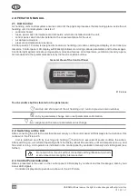
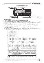
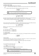
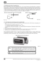
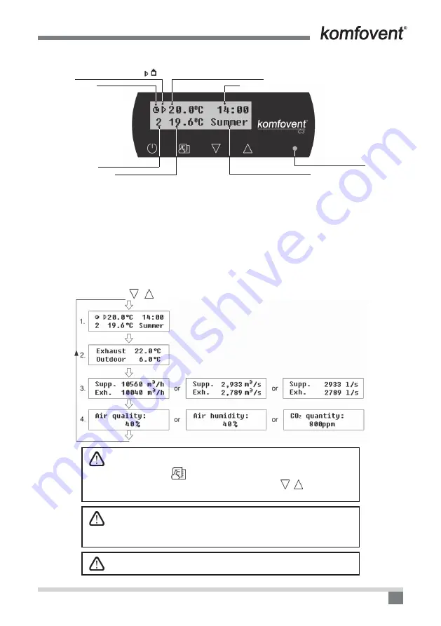
Control Panel Start-Up Window
Temperature mode symbols ( , )
Automatic mode symbol
Setting temperature (+15...30 °C)
Time
Current season (Winter / Summer)
Ventilation level (0,1, 2, 3)
Supply air temperature
Unit operation indication LED
2.3 Picture
Light Diode Indication:
1. No LED signal indication on the panel –
unit has been switched off.
2. LED shines steady green and text message is shown –
unit is switched on.
3. Automatic mode symbol is shown on the panel, while green LED shines –
unit is operating in automatic
mode according to weekly schedule.
4. LED blinks red and green and text message is shown – see 7.9 chapter.
5. LED shines steady red and text message is shown –
emergency unit shut down
(see 7.9 chapter).
6. Nothing is showing on the control panel -
unit does not have electric power supply.
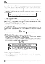
2.4. Parameters Review
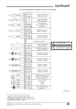
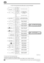
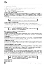
Main parameters are shown in the start-up window (2.3. Picture). To view other parameters (temperature value
or air flow indication) touch
,
buttons till corresponding window appears:
The 3rd window is provided only in the units with EC fans. There is pos-
sibility to change air flow indication from m
3
/h to m
3
/s or l/s. All you need
to do is to press
button while being in an air flow indication window
and holding this button go “up” and “down” with , buttons till you
select the right measures.
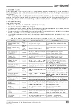
The 4th window is provided only in the units with EC fans. Depending
on the type of mounted air quality sensor, the 4th window may appear in
one of three ways. It appears when air quality function is activated (see
Air quality function setting).
Exhaust air temperature and flow are not displayed for OTK units.
Summary of Contents for C3
Page 2: ......


