UAB AMALVA we reserve the right to make changes without prior notice
23
C3-16-01-v1
1.4. Temperature Sensors Installation
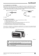
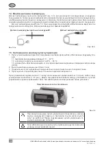
Supply air temperature sensor B1 (1.4 a Picture) is mounted in the air duct in a projected place for it; after
electric heater or cooler section (if provided). The minimal distance from the air vent of the unit up to the sensor
should be not less than double diameter of the circular connection or a diagonal of rectangular connection.
Water temperature sensor B5 (1.4 b Picture) is mounted on the return water pipe by screwing it into the pro-
vided hole. It is recommended that the sensor would be thermo insulated!
Supply air temperature sensor B1
1.4 a Picture
Return water temperature sensor B5
1.4 b Picture
1.5. Control Panel Installation
1. Control panel must be installed in the room under given following conditions:
1.1. ambient temperature range 0 °C ... 40 °C;
1.2. relative humidity limits 20 % … 80 %;
1.3. protection must be ensured from accidentally vertically falling water drops (IP X2).
2. Installation height must be not less than 0,6 m from the ground.
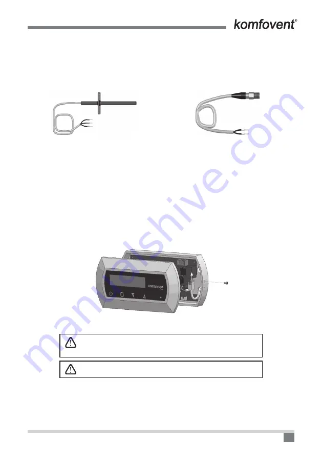
3. Control panel connection is projected through the hole in its backside.
4. Control panel is fixed after screwing two holes on the fastening surface.
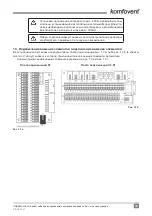
Control panel is connected to the connection box terminals (see 1.3 a Picture) to the provided terminals
(1.3 b Picture). The length of the cable between the control panel and the unit should not exceed 150 m. Cable
type is specified in unit wiring diagram.
Control Panel Connection
1.5 Picture
When closing the panel window, do not bend the springs inside as this
may inhibit the functions of the panel buttons! Disconnect power supply
prior to connecting the control panel!
Control panel connection and other cable thicknesses are specified in
the wiring diagram!
Summary of Contents for C3
Page 2: ......

