SIA KOMFOVENT reserves the right to make changes without prior notice
Fire damper UVA60 H / UVA120 H installation manual 21-01
9
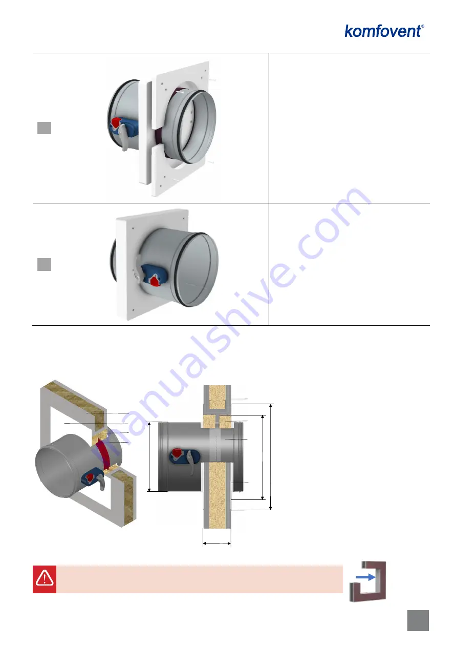
Using four ISO 7049 screws [
7
], join shield flanges
[
2
] to the previously installed shield flanges [
1
].
The junctions of the two flanges should not
overlap, but are at 90°.
Pre – installed Dry montage kit on the damper
casing.
2.4.
Installation in a flexible wall (metal stud drywall)
Internal face of the square opening must be also coated with 2 mm thick fire-resistant coating with min. fire
resistant capacity EI 120 for all installations in a flexible wall
1.
Fire damper UVA 120H (Ø100 ÷ 315)
2.
Flexible wall (metal stud drywall, min. 100 mm
thick)
3.
Mineral wool, min. 100 mm thick, min. density
140 kg/m
3
4.
Layer of fire stopping coating with at least B1
fire resistance
1
.
F
i
r
e
d
a
m
p
e
r
U
V
A
1
2
0
H
3
4
EIS 60 (for size range Ø100 ÷ 315 mm)
D
no
m
+
8
0
D
nom
1
1
2
2
3
3
4
4
Installation steps:
- prepare square installation opening D
nom
+80
mm
-
use a mounting accessorize to secure the
damper in the installation opening
- fill the gap between wall and casing of the
damper with mineral wool and remove the
mounting accessorize
- cover the mineral wool (overlapped the wall)
with stopping mastic.
D
n
om
+
1
6
0
min 100
Summary of Contents for UVA120 H
Page 1: ...2021 ...


