SIA KOMFOVENT reserves the right to make changes without prior notice
Fire damper UVS120 H (Two-Bladed design) ∙
I
nstallation manual ∙ 21-01
11
Installation steps:
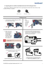
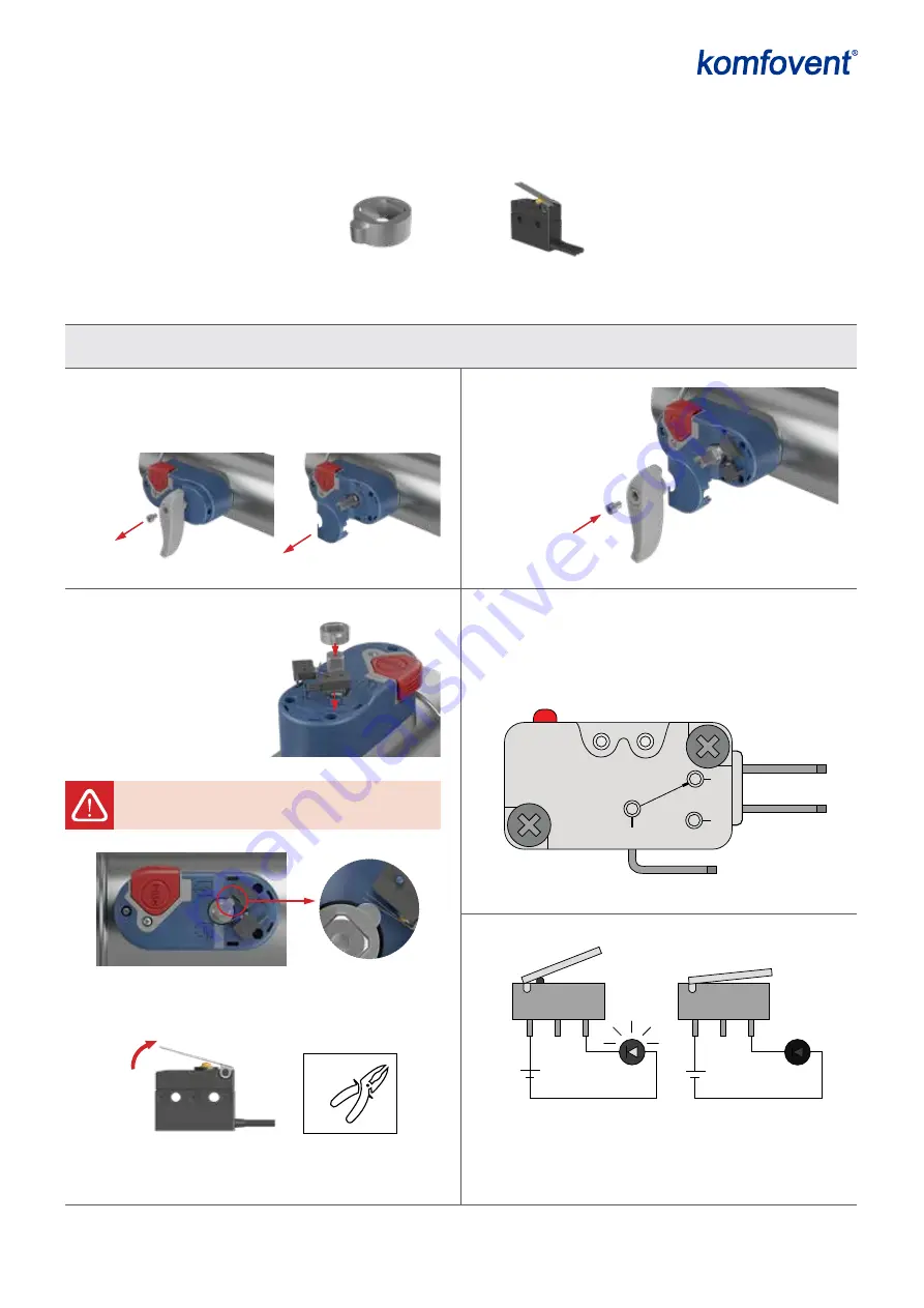
4.1. Signalling devices (switches) installation instructions for fire dampers UVS-H
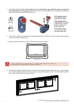
If fire damper is additionally completed by one or two signaling devices (microswitches) and switch cam, simple
installation of the parts is required:
Switch cam – 1 pc.
Microswitch – 1 or 2 pcs.
1. Unscrew damper’s handle holding screw DIN 912,
then remove handle and cap.
2. Place switch cam to
the axis and one or
two microswitches
to the indicated
positions. Make sure
that the cam ledge
pushes the microswi-
thes’ metal plate.
3. Place
switch cam
and handle
back and
screw in
DIN 912
screw.
4. Connect microswitches to designed way. Each
microswitch has NC (normally closed), NO (nor-
mally open) and C (common) poles. Connection
scheme using signaling device:
Using an appropriate tool (e.g. pliers), GENTLY
fold the metal plate as shown:
ACTION SHOULD BE TAKEN IF THE CAM DOESN’T PUSH
THE METAL PLATE:
Avoid to fold the plate too hard so it can be broken!
C
NO
NC
3-30 V
C
NO
NC
3-30 V
Each microswitch has NC (normally closed), NO
(normally open) and C (common) poles. Connection
scheme using signaling device is shown
Tool:
3-5°
Screw:
DIN 912 M6x10
1
2
3
NC
NO
COM
Normally Closed
Normally Open
Common


