L
L
H
SIA KOMFOVENT reserves the right to make changes without prior notice
Fire damper UVS120 H (Two-Bladed design) ∙
I
nstallation manual ∙ 21-01
7
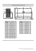
H, mm
L, mm
450
15
500
40
550
65
600
80
650
115
700
140
750
165
800
190
850
215
900
240
950
265
1000
290
4. INSTALLATION STEPS
Before starting installation process any fire damper shall be inspected for damages by responsible person!
The installation process must include the following steps:
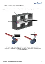
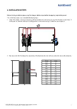
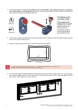
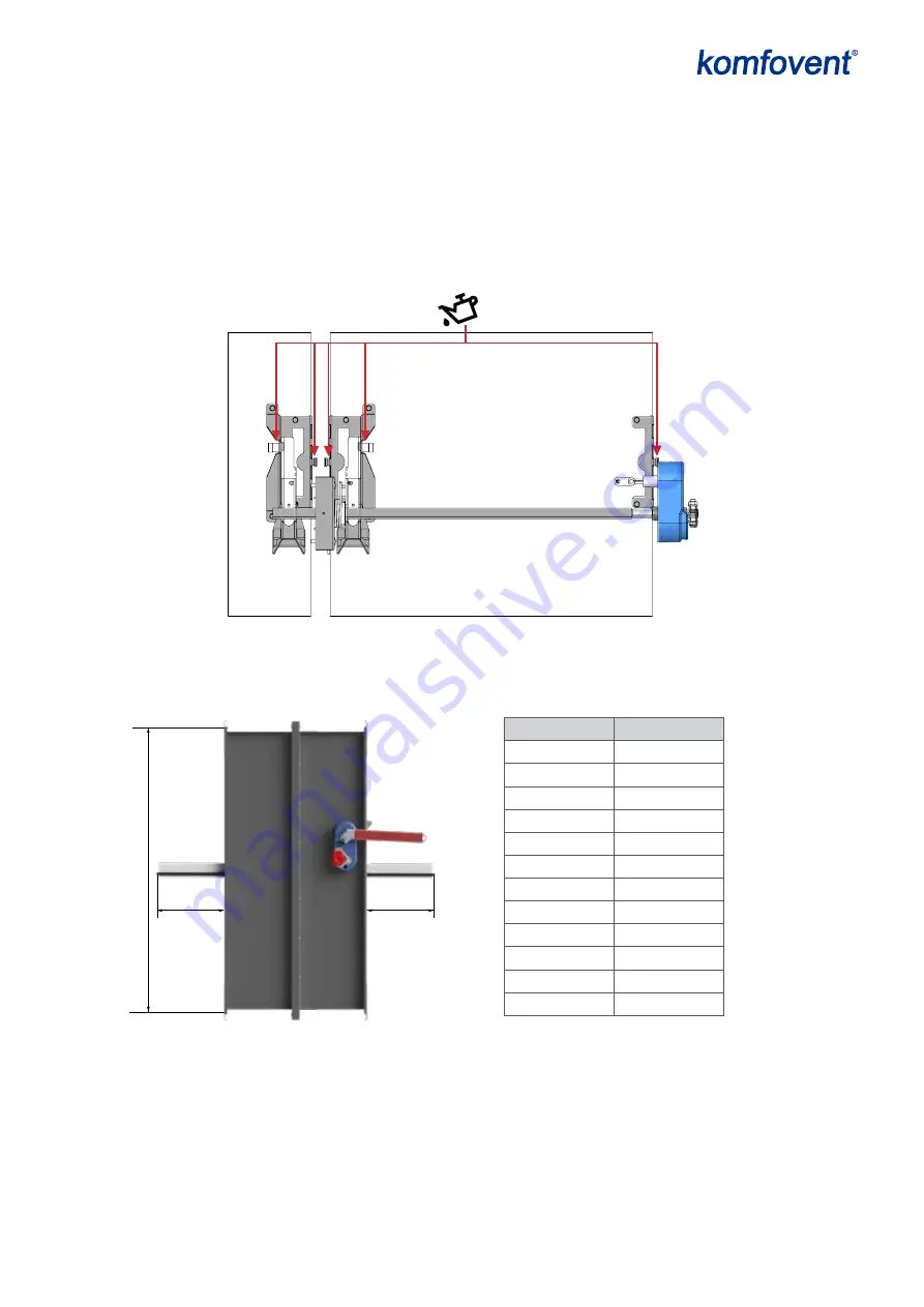
1. Check if the blade is closing and opening without additional resistance by pressing “Push’ button several times. If
sticking occurs, lubricate rotation and sliding points as shown below using a suitable amount of grease:
2. Please consider that fire damper has exposition of the blade into the duct within a certain distance in either direction:


