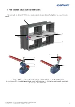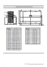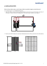
≥75
≥200
≥75
B+60
0
+30
H+60
0
+30
SIA KOMFOVENT reserves the right to make changes without prior notice
Fire damper UVS120 H (Two-Bladed design) ∙
I
nstallation manual ∙ 21-01
8
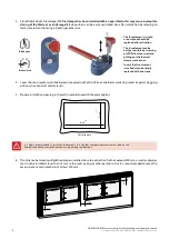
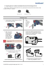
3. Close the blade of a fire damper.
If a fire damper has been installed with an open blade, this may cause incomplete
closing of the blade or even damage!
Blade position can be easily controlled also after installation by referring to
marks located on the casing of locking mechanism:
•
The fuse element is single-
use only and should be
replaced after activation.
•
The fuse element can be
easily accessible by screwing
out PUSH button screw and
pulling out the thermal
release mechanism.
•
In case the fuse element
is melted it can be simply
replaced with a new one.
Blade open
Blade closed
4. Cover the main mechanism (if delivered uncovered) with plastic film or another material to protect it against clogging
with construction dust and materials.
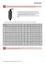
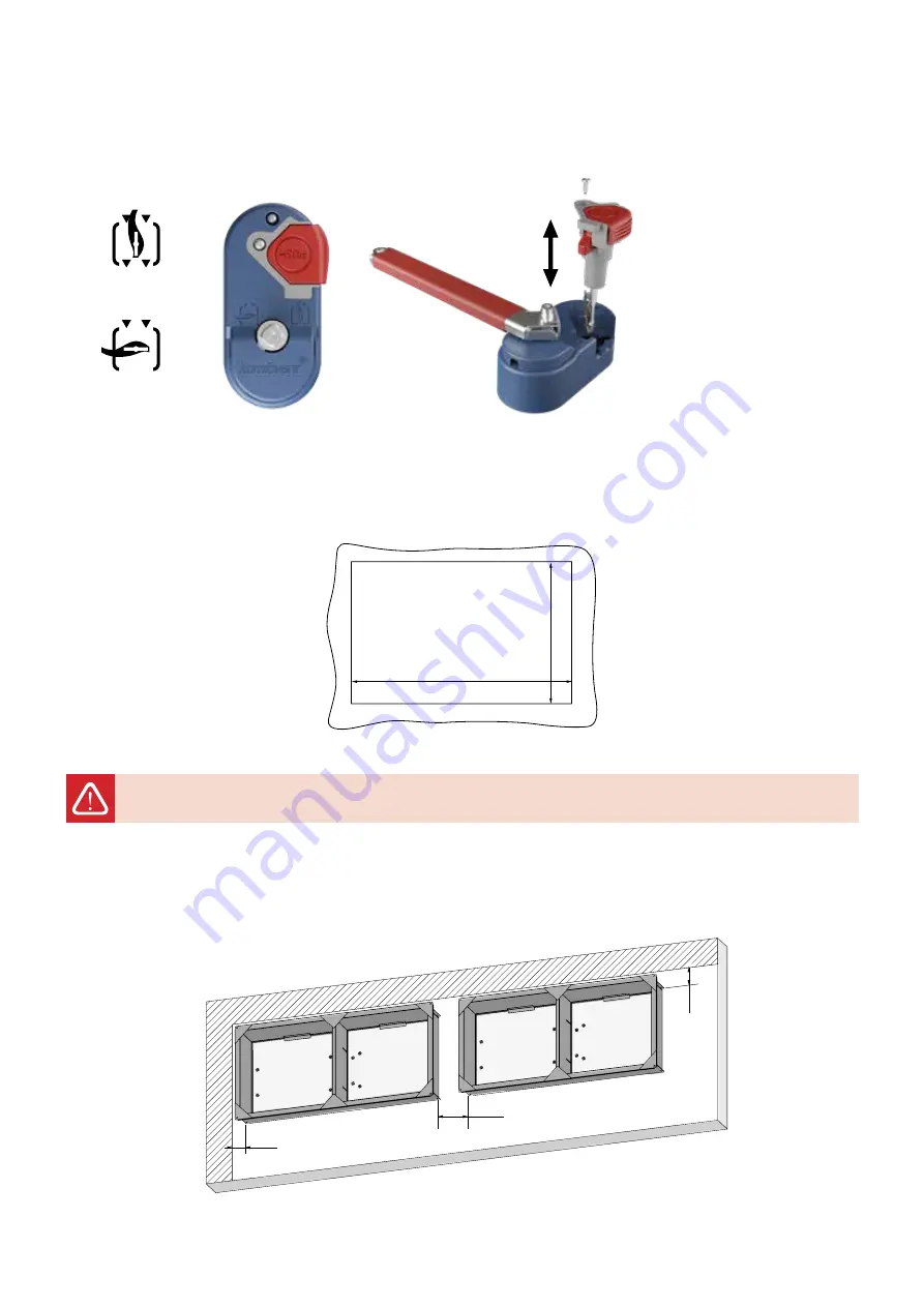
5. Prepare installation opening in the wall in accordance with the prescriptions:
It is highly recommended to install the fire dampers in a way that completely prevents excess load on the
dampers and transfer any load from ducts or supporting constructions!
For solid walls
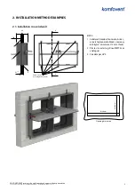
6. The distance between multiple fire dampers installed close to each other shall not exceed 200 mm, as well as damper
must not be installed closer than 75 mm to the walls, ceiling or other partitions, but it is recommended to leave the
access space to main mechanism at least 300 mm.


