37
UAB KOMFOVENT we reserve the right to make changes without prior notice
VERSO STANDARD_21-02
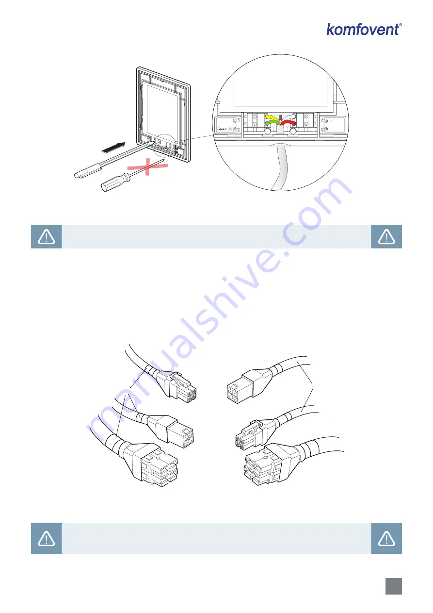
Yellow (A
)
(+) Red
Green (B)
( ) White
Yellow (A)
( ) White
(+) Red
Fig. 23.
Control panel cable wiring
Do not use sharp tools for pinning contacts in the control panel (e.g., screwdriver). Please use a pencil
or a ballpoint pen.
6.4. Connection of Cables and Wires Between Sections
Before fastening sections of the larger air handling units together, you shall connect connecting cables and wires in
between of the sections. Cable connectors are labelled with connector numbers; only connect connectors with the same
number. Number of cables and connectors in different sections may differ depending on fitted components. If any features
or external components are not ordered, there may be some uncoupled connections between the sections. Refer to the wir-
ing diagram of the specific unit to see what connections should be used.
X1
X2
X12
X1
X2
X12
2
3
1
Fig. 24.
Cable connections between sections
1 – power supply cable, 2 – communication cables between circuit boards 3 – labels with connection numbers
Connected wires and cables must be inspected to ensure that they will not accidentally disconnect
due to vibrations of the unit or get in contact with moving parts of the unit (fans, valves, rotor wheel).
If necessary, use special ties to attach the wires to the unit housing.


