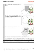
9
At the DynA45 006 frequency converter; Set
P3.9
=current limit to 8.4A. This is the maximum allowed
temporary over current for one minute of time.
10
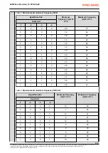
Set the control mode. The control mode settings in DynADrive 022 and the corresponding parameter
value for DynA45 006 are given in table 6.
Table 10. Control mode
DynADrive 022
Control Method
DynA45 006
Switch S6
Parameter
-1
-2
P6.1
0
0
MS2
2
1
0
EP2
1
11
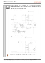
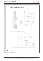
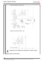
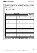
Set travel limit operation settings. See chapter
New frequency controller installation (page 12)
, step 9,
how the control wiring was in the old inverter and how the new inverter wiring was done. In the new
inverter you need to set correct parameters in order to set travel limits to work. After setting the
parameters, test the limit functions.
Old DynADrive 022 inverter
control board connections
Original limit
settings
DynA45 006 parameter
P6.2
P6.3
P6.4
X1:4 / DIA4
X1:5 / DIA 5
S11 , S21
3
0
1
X1:4 / DIA4
X1:5 / DIA 5
OL10
0
X1:3 / DIA3
S11, S21
3
12
At the DynA45 006 frequency converter; set parameter
P1.1
to value 0. This sets the default password
level which doesn't allow any changes to the parameters .
020145en / Revision D / 2015-04-29
25/31
This document and the information contained herein, is the exclusive property of Konecranes Plc. and represents a non-public, confidential and proprietary trade secret that may not be
reproduced, disclosed to other parties, altered or otherwise employed in any manner whatsoever without the express written consent of Konecranes Plc.
Copyright
©
(2014) Konecranes Plc. All rights reserved.


