background image

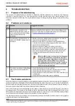
Code

Fault

Possible cause

Suggested solution

Resetting

53

CAN
Communication
Fault

• CAN Communication is not

working

• Switch off supply voltage

from all devices that are
connected to CAN bus

• Check CAN-bus wiring and

termination resistor settings

• Check CAN-communication

parameters

C

55

Board Fault

• API3 is not installed or not

working properly

• Switch off supply voltage
• Check API3 supply voltage
• Check API3 wiring

connections

• If problem recurs, replace

inverter

B

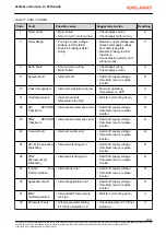
56

Generator  Current
Limit/Deceleration
Ramp Supervision

• Inverter cannot stop with the

set ramp stretching

• Increase P1.8 Deceleration

Time or P11.1 Ramp
Stretching value

C

57

Motor
Overtemperature

• Motor temperature too high
• Digital input DIA4

deactivated when used for
motor overtemperature
protection

• Wait for motor cooling down
• Avoid running long periods at

low speed

• Check motor temperature

protection wiring

C

58

Overvoltage
Regulator Timeout

• Overvoltage regulator has

been active for 5 sec


C

59

Overvoltage at Start • Too high supply voltage

• Measure supply voltage and

check hoist supply voltage
from hoist type plate

C

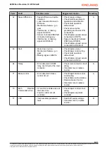
60

Power unit fault

• Power unit has stopped

running

• E-stop during running

• Switch off supply voltage
• Check power unit wiring
• If problem recurs, replace

inverter

B

61

Overspeed

• Overspeed situation detected
• Interference in speed signal

connected to ENC1A

• Check supply voltage
• Check load measurement

operation and calibration

• Check sensor cable

grounding and inverter PE-
connections

• Check/replace speed sensor

connected to ENC1A

A

020145en / Revision D / 2015-04-29

28/31

This document and the information contained herein, is the exclusive property of Konecranes Plc. and represents a non-public, confidential and proprietary trade secret that may not be
reproduced, disclosed to other parties, altered or otherwise employed in any manner whatsoever without the express written consent of Konecranes Plc.
Copyright 

©

 (2014) Konecranes Plc. All rights reserved.

Summary of Contents for DMCS022

Page 1: ...ned herein is the exclusive property of Konecranes Plc and represents a non public confidential and proprietary trade secret that may not be reproduced disclosed to other parties altered or otherwise...

Page 2: ...trol voltage front resistor 11 4 5 New frequency controller installation 12 5 COMMISSIONING 19 5 1 Old inverter parameter settings 19 5 2 Motor type 19 5 3 Traveling motor rating plate values 19 5 4 S...

Page 3: ...the upgrade kit usage This upgrade kit is designed only for DynADrive 022 frequency converter 1 3 Waste treatment and recycling of removed material The removed parts and packaging material shall be r...

Page 4: ...ing live electrical circuit can cause serious injury Even though main switch is turned off there may still be voltage inside electrical devices such as inverters Wait at least 5 minutes before opening...

Page 5: ...1 pcs Part 4 Wire end ferrule 2 5mm 10 pcs Part 5 M5 x 10 Flanged screw 10 pcs 020145en Revision D 2015 04 29 5 31 This document and the information contained herein is the exclusive property of Kone...

Page 6: ...04 29 6 31 This document and the information contained herein is the exclusive property of Konecranes Plc and represents a non public confidential and proprietary trade secret that may not be reproduc...

Page 7: ...limit direction 1 4 Common slowdown Slowdown Stop limit direction 1 4 Slowdown Stop limit direction 2 5 Common stop Slowdown Stop limit direction 2 5 Common DI1 5 6 Motor temperature protection Exter...

Page 8: ...r package KC310 KC330 whereas DynA45 has an internal EMC filter in the power supply By default the EMC level of the frequency converter is set to N by the manufacturer If the mains network is non grou...

Page 9: ...perty of Konecranes Plc and represents a non public confidential and proprietary trade secret that may not be reproduced disclosed to other parties altered or otherwise employed in any manner whatsoev...

Page 10: ...roller WARNING High voltage inside the Frequency converter Wait for at least five minutes after the voltage supply has been switched of before taking any service actions 3 DynA45 006 has an internal E...

Page 11: ...r 6 must be connected to OL10 via MSL 5 Loosen and remove the screws 4 pcs holding the DynADrive 022 Remove the DynADrive 022 and the EMC filter from the enclosure Note The old screws are self tapping...

Page 12: ...resistor wire from the braking resistor to the cubicle 2 Put 4 pcs size M5 x 10 Flanged installation screws into back plate Leave screws loose The installation rack has slotted screw holes 020145en Re...

Page 13: ...nimum of 2 5 mm This extra grounding wire is not delivered with the package 8 If the DynADrive 022 has an external braking resistor Remove the internal braking resistor wires and connect the braking r...

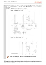
Page 14: ...re 2 New inverter MS2 stop Digital input 5 in DynA45 will be deactivated No connection is needed 020145en Revision D 2015 04 29 14 31 This document and the information contained herein is the exclusiv...

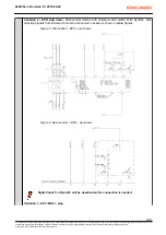
Page 15: ...l be deactivated No connection is needed Variation 3 EP2 MS2 stop 020145en Revision D 2015 04 29 15 31 This document and the information contained herein is the exclusive property of Konecranes Plc an...

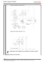
Page 16: ...n D 2015 04 29 16 31 This document and the information contained herein is the exclusive property of Konecranes Plc and represents a non public confidential and proprietary trade secret that may not b...

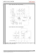
Page 17: ...ies 020145en Revision D 2015 04 29 17 31 This document and the information contained herein is the exclusive property of Konecranes Plc and represents a non public confidential and proprietary trade s...

Page 18: ...formation contained herein is the exclusive property of Konecranes Plc and represents a non public confidential and proprietary trade secret that may not be reproduced disclosed to other parties alter...

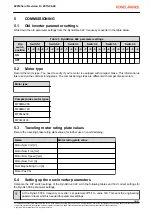
Page 19: ...ther use on commissioning Name Motor rating plate value Motor Nom Volt V Motor Nom Freq Hz Motor Nom Speed rpm Motor Nom Curr A Nom Magnetizing Curr A Motor Cos Phi 5 4 Setting up the new inverter par...

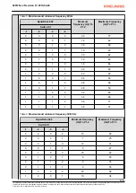
Page 20: ...ynADrive 022 Minimum frequency Hz To P1 2 Maximum Frequency Hz To P1 3 Switch S1 1 2 3 4 0 0 0 0 29 100 0 0 0 1 14 50 0 0 1 0 23 62 0 0 1 1 10 54 0 1 0 0 32 80 0 1 0 1 12 58 0 1 1 0 16 66 0 1 1 1 18 7...

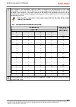
Page 21: ...imum frequency Hz To P1 2 Maximum Frequency Hz To P1 3 Switch S1 1 2 3 4 0 0 0 0 15 50 0 0 0 1 7 25 0 0 1 0 12 31 0 0 1 1 5 27 0 1 0 0 16 40 0 1 0 1 6 29 0 1 1 0 8 33 0 1 1 1 9 35 1 0 0 0 25 58 1 0 0...

Page 22: ...2015 04 29 22 31 This document and the information contained herein is the exclusive property of Konecranes Plc and represents a non public confidential and proprietary trade secret that may not be re...

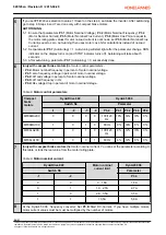
Page 23: ...s DynADrive 022 Acceleration and deceleration Ramp Time s Switch S3 1 2 3 4 0 0 0 0 2 5 0 0 0 1 3 5 0 0 1 0 3 0 0 1 1 5 0 1 0 0 2 0 1 0 1 8 0 1 1 0 1 0 1 1 1 7 5 1 0 0 0 1 5 1 0 0 1 4 1 0 1 0 7 1 0 1...

Page 24: ...f mid frequency in Hz P4 4 Rs voltage drop in percent of motor nominal voltage Table 8 Motor control parameters Compact brake motors DynADrive 022 DynA45 006 Switch S4 Parameter 1 2 3 4 P3 2 P4 1 P4 2...

Page 25: ...to set travel limits to work After setting the parameters test the limit functions Old DynADrive 022 inverter control board connections Original limit settings DynA45 006 parameter P6 2 P6 3 P6 4 X1...

Page 26: ...th frequency converter controlled cranes is not recommended 3 The motor runs poorly trolley bridge does not move as it supposed to move Check that the load is not over nominal Check that all cables ar...

Page 27: ...lem recurs replace inverter B 24 Counter fault Internal counter error Switch off supply voltage If problem recurs replace inverter B 25 API Microprocessor Watchdog Internal watchdog error Switch off s...

Page 28: ...ion wiring C 58 Overvoltage Regulator Timeout Overvoltage regulator has been active for 5 sec C 59 Overvoltage at Start Too high supply voltage Measure supply voltage and check hoist supply voltage fr...

Page 29: ...ror detected in ROB1 relay test circuit or the main contactor Check main contactor circuit wiring If problem recurs replace inverter A 71 Brake control Error detected in brake control circuit Check re...

Page 30: ...of range Check repair load sensor wiring Check replace load sensor C Resetting column explanation A E stop activation deactivation B Hoist supply voltage switch OFF ON C Automatic when fault situatio...

Page 31: ...d in CAN bus has an active fault 93 CCU activation Controlled common use activation Another device that is connected in CAN bus has caused the stopping 020145en Revision D 2015 04 29 31 31 This docume...

Reviews: