4
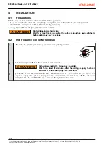
Disconnect and mark the motor supply wires (U, V and W) with cable markers. If the DynADrive 022
has an external braking resistor, disconnect the braking resistor wires and remove the braking resistor.
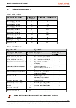
Disconnect the control wires and mark them according to the next table.
Pin in
DynADrive 022
Connect to pin number in DynA45 006
Function
1
1
Drive command, direction 1
2
2
Drive command, direction 2
3
3
Speed 2 / Acceleration command
4
4
Slowdown/stop limit, direction 1
5
5
Slowdown/stop limit, direction 2
6
7
Common for Digital Inputs
7*
8
Normally open relay contact
8*
9
Normally open relay contact
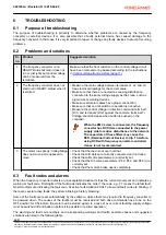
10**
Connect to OL10 signal
Supply voltage for motor bi-metal
thermal protection
11**
6
Motor thermal protection
*) If there are no wires connected in pins 7 and 8 in DynADrive 022 , the relay is not in use and thus
must not be marked.
**)If the pins 10 and 11 are connected together, the motor thermal protection is not in use and thus
pin number 6 must be connected to OL10 signal. If there are two motors, there are two thermal
protection circuits which must be connected in series.
If there is a thermistor installed in the motor, a thermistor relay ,e.g. MSL, must be installed to
thermal protection circuit of the motor. Pin number 6 must be connected to OL10 via MSL.
5
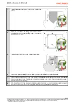
Loosen and remove the screws (4 pcs) holding the DynADrive 022 . Remove the DynADrive 022 and
the EMC-filter from the enclosure. Note: The old screws are self-tapping so they must not be re-used.
Use the delivered screws (part 8) instead.
6
Strip all the wires up to 10 mm. If the wires have thin strands, use wire end ferrules (Part 21) as shown
in the picture.
4.3
Control voltage front resistors
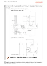
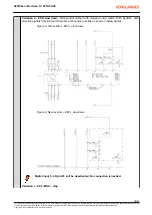
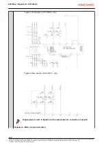
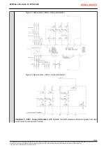
The control voltage range in the DynADrive 022 was 48V - 115V. If the control voltage was 230V, the front
resistors were used to decrease the control voltage to 115V or 48V. In the DynA45 006 the control voltage
range is 42V - 230V. Therefore you must remove or by-pass the possible front resistors when upgrading the
DynADrive 022 to DynA45 006 .
If the front resistors are not removed or by-passed, the control inputs on the DynA45 006
frequency converter are not activated, even though voltage can be measured with a
multimeter.
4.4
By-passing the control voltage front resistor
020145en / Revision D / 2015-04-29
11/31
This document and the information contained herein, is the exclusive property of Konecranes Plc. and represents a non-public, confidential and proprietary trade secret that may not be
reproduced, disclosed to other parties, altered or otherwise employed in any manner whatsoever without the express written consent of Konecranes Plc.
Copyright
©
(2014) Konecranes Plc. All rights reserved.


