26
322217/G
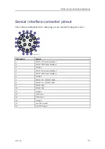
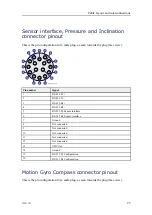
Pin number
Signal
1
TD +
2
TD –
3
RD +
4
RD –
5
RS-232 Tx Sensor interface 3
6
RS-232 Rx Sensor interface 3
7
Ground
8
COM2_OUT
9
COM3_IN_A
10
DC Out Ground
11
VDC Out 24V
12
VDC In
13
DC In Ground
14
Remote On/Off
15
RS-232 Tx Sensor interface 1
16
RS-232 Rx Sensor interface 1
Setup
For deck calibration purposes or to use with a ROV display, the EM3000 telegram
containing heading, pitch, roll and heave is communicated through the 16 pin Seaconn
connector. The data is sent through the RS–232 port COM2_OUT (pin 8 Tx, pin 7
GND). The communications parameters are 9600/8/n/1 with a 10 Hz update rate.
The ON/OFF signal (pin 14 ON/OFF, pin 13 Ext power GND) can be interfaced to
a ROV switch to manually turn external power to the MGC on or off by a ROV.
External power supply is also turned on by the cNODE transponder when enabling
the MGC sensor, but the ROV switch and ROV display output is a backup solution if
the transponder is not working.
For deck test with internal battery only, the MGC sensor must be activated by using a
TTC30 sending an enable sensor command.
Kongsberg cNODE Instruction Manual
Summary of Contents for cNODE Maxi
Page 1: ...Instruction Manual cNODE Maxi and Midi Transponders Medium Frequency 4000 metres ...
Page 2: ......
Page 69: ...322217 G 67 Differential inclinometer arrangement drawing About drawings ...
Page 70: ...68 322217 G Current meter arrangement drawing Kongsberg cNODE Instruction Manual ...
Page 98: ... 2019 Kongsberg Maritime ...

