background image

322217/G

63

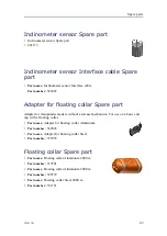
Inclinometer sensor Spare part

• Inclinometer sensor Spare part

• 441115

Inclinometer sensor Interface cable Spare
part

Part name:

Inclinometer sensor Interface cable

Part number:

322407

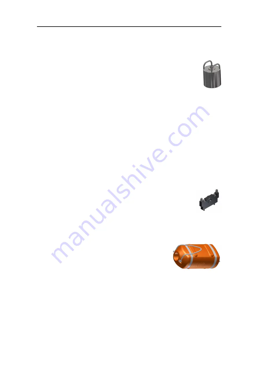
Adapter for floating collar Spare part

Adapter for transponder models without a release mechanism. For use on a basic end
cap with a floating collar.

Part name:

Adapter for floating collar Aluminium

Part number:

369045

Part name:

Adapter for floating collar Steel

Part number:

372953

Floating collar Spare part

Part name:

Floating collar Aluminium 4000 m

Part number:

319301

Part name:

Floating collar Aluminium 2000 m

Part number:

320772

Part name:

Floating collar Steel 4000 m

Part number:

331151

Spare parts

Summary of Contents for cNODE Maxi

Page 1: ...Instruction Manual cNODE Maxi and Midi Transponders Medium Frequency 4000 metres ...

Page 2: ......

Page 3: ...322217 G August 2019 Kongsberg Maritime AS Kongsberg cNODE Maxi and Midi Medium Frequency 4000 m Instruction Manual ...

Page 4: ... designed Improper use or maintenance may cause damage to the equipment and or injury to personnel You must be familiar with the contents of the appropriate manuals before attempting to operate or work on the equipment Kongsberg Maritime disclaims any responsibility for damage or injury caused by improper installation use or maintenance of the equipment Disclaimer Kongsberg Maritime AS endeavours ...

Page 5: ...INTERCONNECTIONS 21 External signal connector pinout 22 Sensor interface connector pinout 23 Inclinometer connector pinout 24 Sensor interface Pressure and Inclination connector pinout 25 Motion Gyro Compass connector pinout 25 Modem interface connector pinout 27 Modem interface connector pinout 28 Jumper settings Modem 28 GENERAL ACOUSTIC CONSIDERATIONS 30 GETTING STARTED 32 Turning on the cNODE ...

Page 6: ...ies 46 Handling transponder and separate transponder batteries in case of an external fire 47 OPERATING PROCEDURES 48 MAINTENANCE 49 Recovering the transponder 50 Battery storage 50 Cleaning the transponder 51 Opening the transponder 51 Inserting an O ring 52 Changing the battery 52 Replacing the sacrificial anodes 54 Resetting the pressure relief valve 54 Lubricating SubConn connectors 54 Closing...

Page 7: ...nder rack Spare part 65 Funnel collar Spare part 65 ABOUT DRAWINGS 66 Differential inclinometer arrangement drawing 67 Current meter arrangement drawing 68 TECHNICAL SPECIFICATIONS 69 Performance specifications 70 Weight and outline dimensions 73 Power requirements 77 Environmental requirements 80 BATTERY SAFETY 81 SECTION 1 Identification 82 SECTION 2 Hazards identification 82 SECTION 3 Compositi...

Page 8: ...6 322217 G SECTION 14 Transport information 88 SECTION 15 Regulatory information 89 SECTION 16 Other information 89 Kongsberg cNODE ...

Page 9: ...thium batteries safety procedure before handling batteries WARNING The transponders are equipped with lithium batteries which can potentially be dangerous Read the lithium batteries safety procedure before handling batteries Important Battery safety ...

Page 10: ...f your cNODE can be downloaded from our website https www kongsberg com maritime Registered trademarks Observe the registered trademarks that apply Windows is a registered trademark of Microsoft Corporation in the United States and other countries HiPAP is a registered trademark of Kongsberg Maritime AS in Norway and other countries cNODE is a registered trademark of Kongsberg Maritime AS in Norwa...

Page 11: ...322217 G 9 Kongsberg cNODE Topics System description page 10 Naming description page 10 Scope of supply page 11 General supply conditions page 12 Support information page 13 Kongsberg cNODE ...

Page 12: ...ry capabilities The transponders are rated to 4000 m with a housing made of coated anodised aluminium or stainless steel The transponders are designed with a modular construction which means that the transducer transponder electronics battery pack and optional add on s can be replaced individually to suit the operation The transponder may be secured to a subsea structure using mounting brackets or...

Page 13: ...ometer sensor Si Sensor interface SiPI Sensor interface Pressure and Inclinometer SvPI Sound velocity Pressure and Inclinometer MGC Motion Gyro Compass Mi Modem Transponder identification The transponders have labels that identifies the transponder name serial number default channels Scope of supply The main units required are provided with the standard delivery Transponder Battery Quick Reference...

Page 14: ...hat Kongsberg Maritime can arrange for replacement or repair of the damaged equipment Once unpacked the equipment must be stored in a controlled environment with an atmosphere free of corrosive agents excessive humidity or temperature extremes The equipment must be covered to protect it from dust and other forms of contamination when stored Equipment responsibility Unless otherwise stated in the c...

Page 15: ... support office in Norway Manuals and technical information can be downloaded from our support website Company name Kongsberg Maritime AS Address Strandpromenaden 50 3190 Horten Norway Telephone 47 33 03 41 00 Telephone 24h support 47 33 03 24 07 Telefax 47 33 04 76 19 Website https www kongsberg com maritime Support website Product support A to Z E mail address km support hpr kongsberg com Kongsb...

Page 16: ...its Topics Transducers page 15 Remote transducers page 15 Modular top section MTS page 17 Modular end caps MEC page 17 cNODE batteries page 19 External sensors page 19 Accessories page 19 Kongsberg cNODE Instruction Manual ...

Page 17: ...onal beam width TD30V30H The transducer has a 30 vertical and a 30 horizontal beam width TD30V The transducer has a 30 vertical beam width Remote transducers The remote transducers are connected to the top of the transponder with a cable TDR180 The transducer has a 180 omnidirectional beam width TDR40V The transducer has a 40 vertical beam width System units ...

Page 18: ...30H The transducer has a 30 horizontal beam width Split for remote transducer The split is the connection between the transponder and the remote transducer Transducer cable The cable connects the transponder and the remote transducer Kongsberg cNODE Instruction Manual ...

Page 19: ...s and accuracies Modem The modem lets you send data acoustically to and from sensors and other equipment The section is available in aluminium Modular end caps MEC Several end caps are available for different needs Basic end cap The basic end cap has a vent screw safety valve a standard external connector and is available in aluminium and stainless steel Release end cap The release mechanism can a...

Page 20: ...nd cap has one set of inclinometers set at 90 to each other X and Y and is available in stainless steel It is available as an end cap or in a combination with an external sensor MGC end cap The Motion Gyro Compass end cap is fitted with a Kongsberg MCG gyro and is available in aluminium for various accuracies Sensor interface Pressure and Inclination end cap The sensor interface pressure and incli...

Page 21: ... sensors are available for different needs Inclinometer sensor The sensor has one set of inclinometers set at 90 to each other X and Y It is available as an end cap or in a combination with an external sensor Current meter Aquadopp is a high accuracy sea current meter The unit is connected to the sensor interface end cap with a subsea cable Accessories Floating collar The floating collars are avai...

Page 22: ...nsponder rack The rack can be used to fasten the transponder to a structure Funnel collar The funnel holds the transponder into place in a structure It has an upper and a lower part Aquadopp mounting clamp The mounting clamp is made for the Aquadopp current meter It keeps the sensor fastened to the transponder Kongsberg cNODE Instruction Manual ...

Page 23: ...ector pinout page 23 Inclinometer connector pinout page 24 Sensor interface Pressure and Inclination connector pinout page 25 Motion Gyro Compass connector pinout page 25 Modem interface connector pinout page 27 Modem interface connector pinout page 28 Jumper settings Modem page 28 Cable layout and interconnections ...

Page 24: ...s seen towards the plug face view Pin 1 2 and 3 is for configuration Pin 4 and 5 is for responder function Pin number Signal 1 RS 232 Tx Configuration 2 Ground 3 RS 232 Rx Configuration 4 Responder trigger 5 Responder trigger 6 On Off 7 Not connected 8 Ground Kongsberg cNODE Instruction Manual ...

Page 25: ... Signal 1 RS 232 Tx Sensor interface 1 2 RS 232 Rx Sensor interface 1 3 Ground 4 RS 232 Tx Sensor interface 3 5 RS 232 Rx Sensor interface 3 6 Ground 7 RS 422 Tx RS 485 Data 8 RS 422 Tx RS 485 Data 9 RS 422 Rx 10 RS 422 Rx 11 Ground 12 VDC Out 1 13 VDC Out 2 14 Ground 15 On Off External 16 On Off Ground Cable layout and interconnections ...

Page 26: ... the inclinometer module via a cable Both modules have the same connector and wiring specifications This is the pin configuration for a male plug as seen towards the plug face view Pin number Signal 1 Pulse width modulation out 2 Ground 3 X 1 4 Y 1 5 X 2 6 Y 2 7 VDC Out Kongsberg cNODE Instruction Manual ...

Page 27: ...RS 422 Rx 4 RS 422 Rx 5 RS 232 Tx Sensor interface 6 RS 232 Rx Sensor interface 7 Ground 8 Not connected 9 Not connected 10 Not connected 11 Not connected 12 Not connected 13 VDC Out 14 Ground 15 RS 232 Tx Configuration 16 RS 232 Rx Configuration Motion Gyro Compass connector pinout This is the pin configuration for a male plug as seen towards the plug face view Cable layout and interconnections ...

Page 28: ...nn connector The data is sent through the RS 232 port COM2_OUT pin 8 Tx pin 7 GND The communications parameters are 9600 8 n 1 with a 10 Hz update rate The ON OFF signal pin 14 ON OFF pin 13 Ext power GND can be interfaced to a ROV switch to manually turn external power to the MGC on or off by a ROV External power supply is also turned on by the cNODE transponder when enabling the MGC sensor but t...

Page 29: ...signal must be connected to GND Modem interface connector pinout This is the pinout for a 6 pin end cap This is the pin configuration for a male plug as seen towards the plug face view Pin number Signal 1 RS 422 Tx RS 232 Tx 2 RS 422 Tx 3 RS 422 Rx RS 232 Rx 4 RS 422 Rx 5 Ground 6 Screen Cable layout and interconnections ...

Page 30: ... 232 Rx 3 Ground 4 RS 422 Tx RS 485 Data 5 RS 422 Tx RS 485 Data 6 RS 422 Rx 7 RS 422 Rx 8 Ground Jumper settings Modem Default jumper setting is for RS 232 and it is possible to change this to RS 422 or RS 485 ON indicates that a jumper is inserted all the others are open Jumper number RS 232 RS 422 RS 485 ST1 ON ON ST2 ON ST3 ST4 ON ON ST5 ON ST6 ON ST7 ON ST8 ON ST9 Kongsberg cNODE Instruction ...

Page 31: ... Jumper number RS 232 RS 422 RS 485 ST10 ON ON ST11 ON ON ST12 ON ON ST13 ON ON ST14 ON ON ST15 ON ST16 ST17 ST18 ON ST19 ON ST20 ON ON ST21 ON ON ST22 ON ON ST23 ON ON ST24 ON ON Cable layout and interconnections ...

Page 32: ...cone of the vessel system Transducer type There are different types of transducers used on the transponders A focused signal gives less footprint coverage The vessel should always be within the signal footprint of the transponder TX Power The ability to detect signals depends on the signal strength The transmission power can be adjusted both for the vessel system and for the transponder Acoustic n...

Page 33: ...and ray bending Changes in sound velocity through the water column caused by changes in the water temperature and or salinity can bend the acoustic signal and make it impossible to reach the vessel General acoustic considerations ...

Page 34: ...er page 36 Installing a sea current meter page 36 Installing a transponder with an MGC end cap page 38 Installing a floating collar page 38 Deploying a transponder with a floating collar page 39 Releasing the transponder manually page 40 Closing the release unit page 40 Adding weight to the release unit page 41 Default transmit power page 42 Extending the battery lifetime page 42 Kongsberg cNODE I...

Page 35: ...ployed Procedure 1 Pull out the plastic locking cord that secures the transducer in place 2 Remove the transducer 3 Remove the transport plug 4 Insert the new battery Inserting the battery at an angle makes this easier Press firmly to make sure the battery is properly inserted 5 Place a bag of dry silica gel desiccant on the top of the battery 6 Switch the on off switch inside the top to on 7 Repl...

Page 36: ...ry 4 Switch the on off switch inside the top to off 5 Replace the top 6 Insert the locking cord by pushing it sideways around the body Pre deployment checks Before deploying the transponder it is important to do the following checks to make sure the operation goes smoothly Prerequisites Before deploying the transponder it is important to do the following checks to make sure the operation goes smoo...

Page 37: ...ing operation c Read the power setting and confirm it is correct for the upcoming operation Changing between responder and transponder mode The transponder can also be used as a responder unit Prerequisites The transponder must be charged before use By default when the cNODE is turned on it is in transponder mode The signal input for the responder function must be between 2 and 6 ms with a positiv...

Page 38: ...ter Always apply grease before mating connectors SubConn connectors should not be exposed to extended periods of heat or direct sunlight If a connector becomes very dry it should be soaked in fresh water before use 5 Make sure both units face the same direction FWD is moulded into the coating of the sensor module on the transponder and it is engraved into the top end cap of the sensor unit 6 Mount...

Page 39: ...e angle is correct in relation to the guiding tracks on the sensor Note The sea current meter s sensor eye must be facing away from the transponder and other structures 2 Mount the sensor to the transponder with a mounting clamp 3 Mount the transponder in the transponder rack by fastening the clamps around the transponder 4 Connect the cable to the unit Always apply grease before mating connectors...

Page 40: ... 4 M8 bolts with a fitting length and strength to install the MGC Procedure 1 Mount the transponder with the transducer having a free line of sight 2 Enter the insulation sleeves into the bolt holes in the base of the unit 3 Enter M8 bolts of fitting length and strength to the sleeves 4 Fasten the bolts Installing a floating collar The transponder must have a release unit or an adapter for a basic...

Page 41: ... lift the transponder by the transponder cage The transponder must be positioned with the transducer upright Make sure there is a clear line of sight between the transponder s transducer and the ship s transducer The minimum length of the sling between the transponder and the weight should be 2 m to avoid the transponder from hitting the weight when it lands on the seabed Procedure 1 Connect the l...

Page 42: ...udden muted click and thud can be heard and felt Result The release unit is now fully opened A Closing the release unit This is how the anchor weight can be attached to the transponder before operation Prerequisites The release unit can be opened manually or acoustically Procedure 1 Place a release link in the release hook A 2 Pull the reset button B down until a firm click is heard and felt Resul...

Page 43: ...e release mechanism might jam the release hook and the transponder could fail to release open Always use a cable tie or safety wire to secure the pin at the shackle A 10 mm B 17 mm C 16 mm D 10 mm It is recommended to use a minimum of 2 m of rope soft or web lifting sling between the D shackle attached to the release unit and the weight to avoid corrosion Another option is to use a minimum of 1 m ...

Page 44: ...ng High Extending the battery lifetime Consider how to save the transponder s battery life before deployment Reduce the transmit power level of the transponder or increase the interrogation interval to extend the battery lifetime Kongsberg cNODE Instruction Manual ...

Page 45: ...ics Safety features page 44 Recovering a failing transponder page 44 Opening a transponder with defect possibly defect battery page 45 Handling a heated or self heated transponder page 45 Handling a transponder with an open relief valve page 46 Handling heated or warm batteries page 46 Handling transponder and separate transponder batteries in case of an external fire page 47 Emergency procedures ...

Page 46: ...ted and is for safety purposes only The operator can release any excess pressure that may have built up inside the transponder Make sure to dry off any water around the screw before opening it The screw is normally opened and closed by hand Recovering a failing transponder Always read the emergency procedures before handling lithium batteries Prerequisites Handle a failing transponder as a possibl...

Page 47: ... in front of or at the back of the unit when you open it 3 Open the transponder in a safe place out on the deck shielded from people and vital equipment 4 If there has been water ingression and the battery is still warm disconnect the battery from the transponder electronics and study the procedure for handling a heated or warm separate battery 5 Wash out the residues from the chemical reaction wi...

Page 48: ...mounts of cold water using a fire hose 4 Repeat this until no gases come out the relief valve and the temperature is low and stable 5 Take out the battery see the emergency procedure for opening a transponder with a possible defect battery Opening a transponder with defect possibly defect battery page 45 6 Wash out the residues from the chemical reaction with water Handling heated or warm batterie...

Page 49: ... transponder away from the fire 2 Cool it down using lots of cold water Cooling down the battery with a large amount of cold water is the only way to reduce or stop the internal chemical reactions or to limit the fire explosions to as few battery cells as possible The chemical reactions fire will continue without additional supply of oxygen so an extinguisher such as Lith X will not work properly ...

Page 50: ...48 322217 G Operating procedures The transponder is operated from the HiPAP operator station APOS Refer to APOS online help for descriptions Kongsberg cNODE Instruction Manual ...

Page 51: ...der page 51 Opening the transponder page 51 Inserting an O ring page 52 Changing the battery page 52 Replacing the sacrificial anodes page 54 Resetting the pressure relief valve page 54 Lubricating SubConn connectors page 54 Closing the release unit page 55 Releasing the transponder manually page 55 Maintenance ...

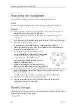
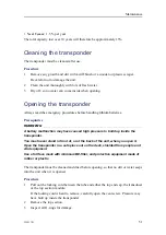
Page 52: ...der for minimum two hours Check for damages that could involve a water leakage and check the housing temperature for a possible temperature increase in the lithium battery For batteries with possible damages go to the emergency procedures chapter 7 Wash the unit thoroughly in warm fresh water to dissolve any salt deposits and clean off any sand or silt 8 As an extra precaution it is recommended th...

Page 53: ... caused high pressure to build up inside the transponder You must never stand in front of or at the back of the unit when you open it Open the transponder in a safe place out on the deck shielded from people and vital equipment Use a full face mask with minimum BE filter and protective equipment made of rubber or plastic The transponder must be cleaned and dried before opening so that no dirt or w...

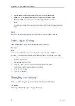
Page 54: ...must be inspected for damage as often as possible Procedure Note Make sure to keep the O rings and mating surfaces free of dust and debris Do not use a screwdriver or similar when removing the O ring use an O ring tool 1 Open the transponder 2 Remove the existing O ring 3 Clean the surface and cover it with a thin film of silicone grease Use lint free objects when cleaning the surfaces 4 Insert th...

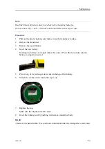
Page 55: ...attery 4 Insert the new battery Inserting the battery at an angle makes this easier Press firmly to make sure the battery is properly inserted 5 Place a bag of dry silica gel desiccant on the top of the battery 6 Switch the on off switch inside the top to on 7 Replace the top Make sure the alignment marks meet 8 Insert the locking cord by pushing it sideways around the body Result A buzz can be he...

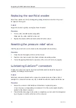
Page 56: ...h the surrounding surface 3 Contact Kongsberg Maritime for assistance if the valve will not reset properly Lubricating SubConn connectors Underwater connectors must be kept clean and lubricated and should be inspected regularly for damages and corrosion Context SubConn connectors should not be exposed to extended periods of heat or direct sunlight If a connector becomes very dry it should be soake...

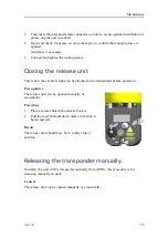
Page 57: ...ght can be attached to the transponder before operation Prerequisites The release unit can be opened manually or acoustically Procedure 1 Place a release link in the release hook A 2 Pull the reset button B down until a firm click is heard and felt Result The release unit should now be in a fully closed position Releasing the transponder manually Normally the unit will be released acoustically fro...

Page 58: ...17 G Procedure Push in the release button C on the side of the release unit A sudden muted click and thud can be heard and felt Result The release unit is now fully opened A Kongsberg cNODE Instruction Manual ...

Page 59: ...ocity Pressure and Inclinometer Spare part page 61 Basic end cap Spare part page 61 Release end cap Spare part page 61 Sensor interface end cap Spare part page 62 MGC end cap Spare part page 62 Inclinometer end cap Spare part page 62 cNODE Maxi Battery Spare part page 62 cNODE Midi Battery Spare part page 62 Inclinometer sensor Spare part page 63 Inclinometer sensor Interface cable Spare part page...

Page 60: ...est and Configuration unit Spare part page 64 Current meter Aquadopp Spare part page 64 Aquadopp mounting clamp Spare part page 64 Transponder rack Spare part page 65 Funnel collar Spare part page 65 Kongsberg cNODE Instruction Manual ...

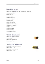
Page 61: ...000 3 locking cords 1 UV plug dummy 6 O rings 107 x 5 mm 1 O rings 10 x 2 mm 1 Vent screw 1 Locking sleeve 1 Transport plug 6 Serrated lock washers TD180 Spare part Part name TD180 Aluminium Part number 319750 Part name TD180 Steel Part number 320877 TD30V30H Spare part Part name TD30V30H Aluminium Part number 313455 Part name TD30V30H Steel Part number 359429 Spare parts ...

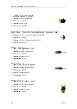
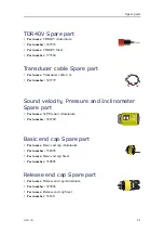
Page 62: ...949 Part name Split for remote transducer Steel Part number 322375 TDR180 Spare part Part name TDR180 Aluminium Part number 349742 Part name TDR180 Steel Part number 375361 TDR30H Spare part Part name TDR30H Aluminium Part number 345773 Part name TDR30H Steel Part number 375359 TDR30V Spare part Part name TDR30V Aluminium Part number 333445 Part name TDR30V Steel Part number 370447 Kongsberg cNODE...

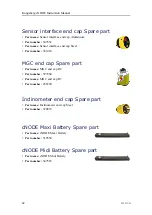
Page 63: ...mber 345772 Sound velocity Pressure and Inclinometer Spare part Part name SvPI Sensor Aluminium Part number 388700 Basic end cap Spare part Part name Basic end cap Aluminium Part number 330498 Part name Basic end cap Steel Part number 330805 Release end cap Spare part Part name Release end cap Aluminium Part number 325026 Part name Release end cap Steel Part number 356511 Spare parts ...

Page 64: ...cap Spare part Part name MGC end cap R2 Part number 397960 Part name MGC end cap R3 Part number 435220 Inclinometer end cap Spare part Part name Inclinometer end cap Steel Part number 320818 cNODE Maxi Battery Spare part Part name cNODE Maxi Battery Part number 319554 cNODE Midi Battery Spare part Part name cNODE Midi Battery Part number 347563 Kongsberg cNODE Instruction Manual ...

Page 65: ...ransponder models without a release mechanism For use on a basic end cap with a floating collar Part name Adapter for floating collar Aluminium Part number 369045 Part name Adapter for floating collar Steel Part number 372953 Floating collar Spare part Part name Floating collar Aluminium 4000 m Part number 319301 Part name Floating collar Aluminium 2000 m Part number 320772 Part name Floating coll...

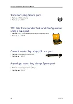
Page 66: ...onfiguration unit Spare part Part name TTC 30 Transponder Test and Configuration unit Part number 345775 Current meter Aquadopp Spare part Part name Aquadopp Current meter Part number 349229 Aquadopp mounting clamp Spare part Part name Aquadopp mounting clamp Part number 351070 Kongsberg cNODE Instruction Manual ...

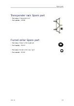
Page 67: ...ansponder rack Spare part Part name Transponder rack Part number 320808 Funnel collar Spare part Part name Funnel collar Upper part Part number 383679 Part name Funnel collar Lower part Part number 383683 Spare parts ...

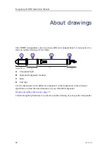
Page 68: ... Split B Optional transponder modules C Body D End caps Use the dimensions of the different components in the transponder in the technical specification to find the total dimension of your cNODE transponder Weight and outline dimensions page 73 Contact Kongsberg Maritime if you need an outline drawing of your specific transponder Kongsberg cNODE Instruction Manual ...

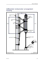
Page 69: ...322217 G 67 Differential inclinometer arrangement drawing About drawings ...

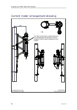
Page 70: ...68 322217 G Current meter arrangement drawing Kongsberg cNODE Instruction Manual ...

Page 71: ...22217 G 69 Technical specifications Topics Performance specifications page 70 Weight and outline dimensions page 73 Power requirements page 77 Environmental requirements page 80 Technical specifications ...

Page 72: ...m Operational frequency Medium frequency 21 31 kHz TD180 Transducer beam 180 degrees Maximum source level 190 dB Receiver sensitivity 100 dB TD30V Transducer beam 30 Vertical Maximum source level 206 dB Receiver sensitivity 85 dB TD30V30H Transducer beam 30 Vertical 30 Horizontal Maximum source level 206 dB 190 dB Receiver sensitivity 85 dB Kongsberg cNODE Instruction Manual ...

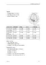
Page 73: ...0 dB 184 dB 178 dB 173 dB 34 30V series 206 dB 200 dB 194 dB 186 dB 34 40V series 203 dB 197 dB 191 dB 185 dB 34 30H series 194 dB 188 dB 182 dB 176 dB Release end cap Safe working load 500 kg Minimum anchor weight 60 kg Connector 8 pin female Subconn MCBH8F Inclinometer end cap Maximum detectable angles 60 degrees Accuracy 0 25 degrees Resolution 0 1 degrees Connector 8 pin female Subconn MCBH8F ...

Page 74: ...cap Connector 8 pin female Subconn MCBH8F Connector 16 pin Subconn MCBH16M Sound velocity Pressure and Inclinometer Digiquartz pressure sensor 1400 m 0 01 of full scale range 2000 m 0 01 of full scale range 4000 m 0 01 of full scale range MTS Inclinometer Accuracy 0 05 degrees Range 90 degrees Sound Velocity Accuracy 0 02 m s Floating collar Depth range Aluminium 2000 m 4000 m Depth range Steel 40...

Page 75: ...t In air Aluminium 4 1 kg Weight In air Steel 8 2 kg TD30V30H Outline dimensions Height 316 mm Diameter 184 mm Weight In air Aluminium 8 3 kg Weight In air Steel 12 9 kg TD30V Outline dimensions Height 169 5 mm Diameter 166 mm Weight In air Steel 9 1 kg Split for remote transducer Outline dimensions Height 62 mm Diameter 166 mm TDR180 Outline dimensions Height 209 8 mm Diameter 88 mm Technical spe...

Page 76: ...eight 279 5 mm Diameter 166 mm Transducer cable Length 6 m Sound velocity Pressure and Inclinometer Outline dimensions Height 184 mm Diameter 144 mm Weight In air 4 6 kg Weight In water 2 kg cNODE Maxi body Outline dimensions Height 805 mm Diameter 144 mm cNODE Midi body Outline dimensions Height 495 mm Diameter 144 mm Kongsberg cNODE Instruction Manual ...

Page 77: ...kg Release end cap Outline dimensions Height 243 mm Diameter 144 mm Weight In air Aluminium 4 9 kg Weight In air Steel 11 3 kg Sensor interface end cap Outline dimensions Height 72 8 mm Diameter 144 mm Weight In air Aluminium 2 4 kg Inclinometer end cap Outline dimensions Height 128 mm Diameter 144 mm MGC end cap Outline dimensions Height 237 mm Diameter 212 mm Weight In air Aluminium 45 kg Weight...

Page 78: ...lar 2000 m Aluminium transponder Outline dimensions Height 949 mm Width 358 mm Depth 300 mm Weight In air 43 kg cNODE Maxi Floating collar 4000 m Aluminium transponder Outline dimensions Height 948 mm Width 350 mm Depth 455 mm Weight In air 69 6 kg cNODE Maxi Floating collar 4000 m Steel transponder Outline dimensions Height 845 5 mm Width 528 mm Depth 595 mm Weight In air 110 kg Kongsberg cNODE I...

Page 79: ...me 913 days cNODE Maxi 34 180 series Cymbal Update rate TX power level 1 second 2 s 3 s 4 s 5 s 10 s Minimum 95 days 101 days 102 days 103 days 104 days 105 days Low 71 days 85 days 91 days 95 days 97 days 101 days High 36 days 54 days 65 days 72 days 77 days 89 days Maximum 10 days 18 days 25 days 32 days 37 days 55 days cNODE Maxi 34 180 series FSK Update rate TX power level 1 second 2 s 3 s 4 s...

Page 80: ... 10 s Minimum 167 days 172 days 174 days 175 days 175 days 176 days Low 125 days 147 days 156 days 161 days 164 days 170 days High 61 days 91 days 109 days 121 days 129 days 149 days Maximum 18 days 34 days 46 days 57 days 66 days 96 days cNODE Midi Battery type Non rechargeable lithium battery Li SOCl2 Operating range 10 14 4 VDC Battery voltage 14 4 VDC Battery capacity 64 Ah Cells per battery 2...

Page 81: ... 4 s 5 s 10 s Minimum 83 5 days 86 days 87 days 87 5 days 87 5 days 88 days Low 70 5 days 78 5 days 81 5 days 83 5 days 84 5 days 86 5 days High 44 days 59 days 66 5 days 71 days 74 days 80 5 days Maximum 15 days 25 5 days 33 5 days 40 days 45 days 59 5 days cNODE Midi 34 30V30H and other series Cymbal Update rate TX power level 1 second 2 s 3 s 4 s 5 s 10 s Minimum 47 5 days 50 5 days 51 days 51 ...

Page 82: ...days 60 5 days 64 5 days 74 5 days Maximum 9 days 17 days 23 days 28 5 days 33 days 48 days MGC end cap External power 9 36 VDC Power consumption Maximum 20 W Typical 12 W cNODE Maxi 72 hours cNODE Midi 36 hours Environmental requirements These specifications summarize the temperature requirements and other environmental standards for the cNODE system Transponder Operating temperature 5 to 55 C St...

Page 83: ...85 SECTION 7 Handling and storage page 85 SECTION 8 Exposure control and personal protection page 86 SECTION 9 Physical and chemical properties page 86 SECTION 10 Stability and reactivity page 87 SECTION 11 Toxicological information page 87 SECTION 12 Ecological information page 88 SECTION 13 Disposal considerations page 88 SECTION 14 Transport information page 88 SECTION 15 Regulatory information...

Page 84: ...gerous or hazardous with normal use The battery must not be opened or burned The battery contains dangerous ingredients Exposure to the ingredients contained within the battery cells could be harmful The battery cells include a barrier preventing exposure to the user and environment The battery cells are not classified as hazardous according to Regulation EC No 1272 2008 The chemicals in the batte...

Page 85: ...tions during an emergency may however clog this pressure release valve SECTION 3 Composition The battery is a solid manufactured article A lithium battery pack consists of several individual cells that are electrical connected both in series and parallel The battery packs have different number of cells and power capacity All transponder batteries include protection against short circuits circuit b...

Page 86: ...e chemicals are skin irritant Rinse immediately with copious amount of water and soap for at least 15 minutes Wipe immediately away excess material with waterless hand cleaner Remove contaminated clothing and wash it thoroughly before reuse Eye contact The chemicals are eye irritant Flush immediately with copious amount of clear tepid water for at least 15 minutes Ingestion Exposure to the chemica...

Page 87: ...elease measures During normal operation accidental release measures are not applicable Extreme mechanical abuse to the battery may result in a ruptured seal and exposure As an immediate precautionary measure isolate the spill or leak area at least 25 metres 75 feet in all directions Keep unauthorized personnel away Stay upwind and keep out of low areas Ventilate closed areas before entering Wear a...

Page 88: ...rborne exposures to hazardous substances are not expected when the battery is used for its intended purpose No protection respiratory skin and or eye is then required If the battery is damaged and you are exposed to the chemicals inside proper personal protection is required In the event of fire or physical damage to the battery follow the mandatory rules for personal protection Fire or explosion ...

Page 89: ... open dissemble crush or burn the battery 2 Do not expose the battery to water sea water or other high conductivity liquids 3 Avoid mechanical or electrical abuse 4 Do not expose the battery to temperatures outside the range of 40 C to 80 C 5 Store in a dry location Recommended relative air humidity is 40 to 70 To minimize any adverse affects on the battery performance it is recommended that it is...

Page 90: ...he same care as new ones Note For safe disposal contact the nearest local company that has been approved to collect and dispose of lithium batteries SECTION 14 Transport information Transportation of the cNODE must be performed in accordance with rules and regulations stated for transportation of dangerous goods in the applicable countries Certification UN 38 3 Transport identification codes Aircr...

Page 91: ... 9 Miscellaneous Lithium batteries Note During transport a lithium battery must always be disconnected from the electronics SECTION 15 Regulatory information Not applicable SECTION 16 Other information The battery manufacturers safety data sheet is available on their website Saft http www saftbatteries com Battery safety ...

Page 92: ...29 TD30V30H 59 361410 sensor interface 62 369045 adapter 63 370447 TDR30V 60 372953 adapter 63 375359 TDR30H 60 375360 TDR40V 61 375361 TDR180 60 383679 upper funnel collar 65 383683 lower funnel collar 65 388700 SvPI 61 397960 MGC R2 62 435220 MGC R3 62 441115 inclinometer 63 A about acoustic considerations 30 acoustic range 30 document downloads 8 online information 8 purpose of this manual 8 re...

Page 93: ...68 installation 68 spare part 64 current meter mounting clamp 351070 64 D default transmitting power 42 default transmitting power 42 deployment description 39 description add weight to the release 41 battery storage 50 close the release 40 55 deployment 39 manual release 40 55 modular top section 17 MTS 17 naming 10 system 10 differential inclinometer arrangement drawing 67 installation 36 67 dim...

Page 94: ...y 52 current meter 68 differential inclinometer 36 67 floating collar 38 MGC 25 38 sea current meter 36 installation requirements environmental 80 temperature 80 interface cable spare part 63 J jumper settings modem 28 L links settings modem 28 lower funnel collar 383683 65 lubricating underwater connector 54 M main items provided with the delivery 11 maintenance kit 345595 spare part 59 spare par...

Page 95: ...eight to the release 41 changing the battery 52 changing to responder mode 35 closing the release 40 55 extending the battery lifetime 42 installing the differential inclinometer 36 installing the floating collar 38 installing the MGC 25 38 installing the sea current meter 36 lubricating the underwater connector 54 manually releasing the transponder 40 55 opening the transponder 51 recovering the ...

Page 96: ... responsibility 12 receipt 12 storage 12 unpacking 12 support information 13 SvPI 388700 61 switch off 34 on 33 system description 10 T target audience this manual 8 TD180 319750 59 320877 59 spare part 59 TD30V 320077 60 320662 60 spare part 60 TD30V30H 313455 59 359429 59 spare part 59 TDR180 349742 60 375361 60 spare part 60 TDR30H 345773 60 375359 60 spare part 60 TDR30V 333445 60 370447 60 sp...

Page 97: ... off 34 on 33 U underwater connector lubricating 54 unpacking general supply conditions 12 upper funnel collar 383679 65 V vessel system about 30 W website download documents 8 weight technical specifications 73 Index ...

Page 98: ... 2019 Kongsberg Maritime ...

Reviews: