background image

14

458122/B

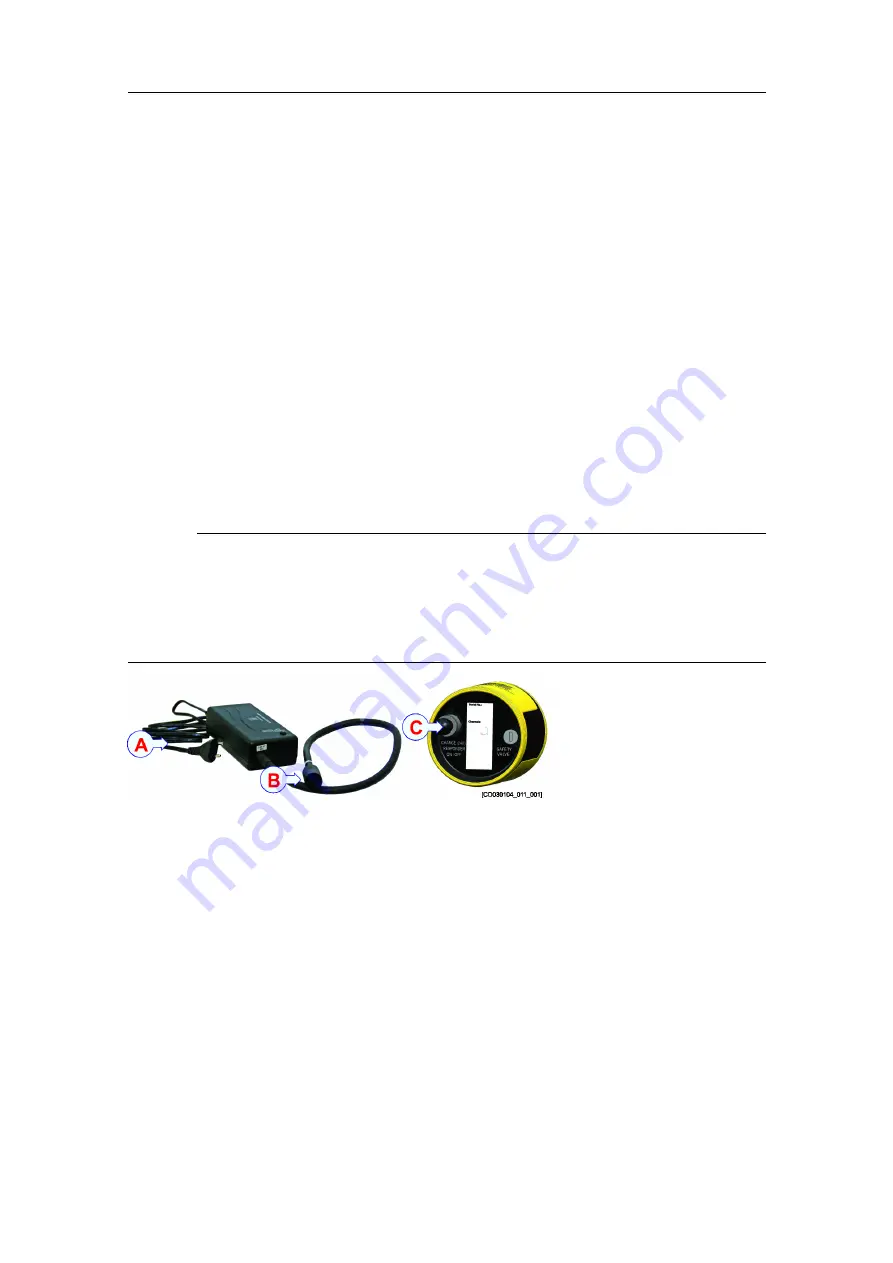
Charging the battery (on-deck)

Charging a battery is a process with an inherent risk so check applicable procedure(s)
prior to charging in order to first assess the level of the inherent risk; and then, if
necessary, apply suitable controls to mitigate the inherent risk before charging. Follow
the charging procedure carefully.

Context

The battery must be fully charged before long term storage and it is recommended
to recharge the battery every 6 months to make sure the battery does not discharge
completely over time. A completely discharged battery will not charge, as all lithium
ion batteries.

To comply with regulations for air transportation, the battery must have 30 % or less
remaining capacity.

The battery charger will only start to charge if the battery capacity is lower than 96 %.

Caution

Equalize the temperature of the cNODE MiniS LF to between 10 °C and 40 °C before
charging it.

For on-deck charging, use the cNODE battery charger only.

Never charge the battery unattended.

Procedure

1

Disconnect the on/off plug from the cNODE transponder.

2

Let the unit warm up or cool down to an ambient temperature of 10 °C to 40 °C
before charging.

3

Connect the battery charger plug (

B

) to the connector on the cNODE MiniS LF

marked CHARGE (

C

).

4

Connect the battery charger to mains (110 or 220 VAC).

5

Remove the power cord after charging, before removing the connector from the
cNODE MiniS LF.

Result

The LED indicator on the charger flashes green when charging. It normally takes about
30 seconds before the charging starts and the LED indicator starts flashing green after

cNODE MiniS LF Instruction Manual

Summary of Contents for cNODE MiniS LF

Page 1: ...458122 B September 2022 Kongsberg Maritime AS cNODE MiniS LF Transponder Instruction Manual ...

Page 2: ...it was designed Improper use or maintenance may cause damage to the equipment and or injury to personnel You must be familiar with the contents of the appropriate manuals before attempting to operate or work on the equipment Kongsberg Maritime disclaims any responsibility for damage or injury caused by improper installation use or maintenance of the equipment Disclaimer Kongsberg Maritime AS endea...

Page 3: ...r and responder signals 16 Changing between responder and transponder mode 17 Turning on the TTC 17 Acoustic test 17 Pre deployment checks 18 Deployment 19 Recovering the transponder 19 Cymbal protocol 20 OPERATING PROCEDURES 21 MAINTENANCE 22 Safety features 23 Charging the battery on deck 23 Replacing the connector 25 Lubricating SEACON connectors 26 Battery charger status and troubleshooting 28...

Page 4: ... Performance specifications 42 Weights and outline dimensions 43 Power requirements 44 Environmental requirements 44 BATTERY SAFETY 45 SECTION 1 Identification 46 SECTION 2 Hazards identification 46 SECTION 3 Composition 47 SECTION 4 First aid measures 47 SECTION 5 Firefighting measures 48 SECTION 6 Accidental release measures 48 SECTION 7 Handling and storage 49 SECTION 8 Exposure control and per...

Page 5: ... https www kongsberg com maritime Registered trademarks Observe the registered trademarks that apply Windows is a registered trademark of Microsoft Corporation in the United States and other countries HiPAP is a registered trademark of Kongsberg Maritime AS in Norway and other countries cNODE is a registered trademark of Kongsberg Maritime AS in Norway and other countries cPAP is a registered trad...

Page 6: ...6 458122 B cNODE MiniS LF Topics System description page 7 Naming description page 7 System units page 8 Support information page 10 cNODE MiniS LF Instruction Manual ...

Page 7: ...itanium They have an internal tilt sensor 90 an external on off function and a pressure relief valve for safety purposes cNODE MiniS LF is powered from an internal rechargeable Li Ion battery and can be powered from ROVs 24 V during operation An on deck battery charger is available Update the configuration and the software via an external connector TTC10 can be used for test and configuration Nami...

Page 8: ...l transponders have an internal tilt sensor 90 and a rechargeable Li Ion battery The transponder can be charged from an on deck battery charger or from a ROV s 24 V during operation Battery charger Charging a battery is a process with an inherent risk so check applicable procedure s prior to charging in order to first assess the level of the inherent risk and then if necessary apply suitable contr...

Page 9: ...ors MCIL4F and MCIL4M The cable connects the remote transducer to the transponder TTC 10 Transponder Test and Configuration unit The transponder test and configuration unit is designed for on deck testing and configuration of the transponders The TTC can test all Kongsberg Transponder low frequency channels Cymbal and FSK It can also test telemetry Transponders with internal and external sensors c...

Page 10: ...act our main support office in Norway Manuals and technical information can be downloaded from our support website Company name Kongsberg Maritime AS Address Strandpromenaden 50 3183 Horten Norway Telephone 47 33 03 41 00 Telephone 24h support 47 33 03 24 07 Website https www kongsberg com maritime Support website Product support A to Z Email address km support hpr kongsberg com cNODE MiniS LF Ins...

Page 11: ...ers depending on operational needs An omnidirectional transducer such as a TD180 covers a large area but has less acoustic power compared to a focused transducer such as TD50V A focused signal gives less footprint coverage The vessel should always be within the signal footprint of the transponder Tx Power The ability to detect signals depends on the signal strength The transmission power can be ad...

Page 12: ...iations in water temperature affects the velocity of sound through the water column and variations in the ocean s salinity level can bend the acoustic signal making it impossible for the signal to reach the vessel cNODE MiniS LF Instruction Manual ...

Page 13: ...15 Connecting the transponder to external power and responder signals page 16 Changing between responder and transponder mode page 17 Turning on the TTC page 17 Acoustic test page 17 Pre deployment checks page 18 Deployment page 19 Recovering the transponder page 19 Cymbal protocol page 20 Getting started ...

Page 14: ...apacity The battery charger will only start to charge if the battery capacity is lower than 96 Caution Equalize the temperature of the cNODE MiniS LF to between 10 C and 40 C before charging it For on deck charging use the cNODE battery charger only Never charge the battery unattended Procedure 1 Disconnect the on off plug from the cNODE transponder 2 Let the unit warm up or cool down to an ambien...

Page 15: ... time Prerequisites The transponder must be charged before use Procedure 1 Grease the connector with Molykote 44 Medium or equivalent grease Lubricating SEACON connectors page 26 2 Connect the on off plug to the end cap connector 3 Tighten the locking sleeve to the end cap connector Result A buzz can be heard within 25 seconds as a confirmation that the transponder is activated Further requirement...

Page 16: ...1 Use the cable with part number 402462 from Kongsberg 2 Connect wire 6 and 8 in the pigtail the ON OFF function When 6 8 are linked the transponder is ON With no connection between 6 8 the transponder is OFF 3 Make sure that the external power supply 24 VDC is between 20 and 28 VDC 4 Check the responder trigger signal 5 Switch ON the unit by inserting the external power responder cable Further re...

Page 17: ...er 2 Once the responder trigger signals stop it will take 1 minute before the cNODE MiniS LF changes automatically back to transponder mode Turning on the TTC Use the Transponder Test and Configuration unit to check that the transponder is ready for use Procedure 1 Open the suitcase 2 Turn on the main power switch to start the program This takes approximately 1 5 minutes Acoustic test Test the tra...

Page 18: ...ith the Test and Configuration unit TTC to make sure it is working properly before operation Procedure 1 Make sure the locking cord is in place 2 If the unit has been altered from the factory pre sets check that the unit is configured according to your requirements 3 Make sure the battery is fully charged 4 Push the pressure relief valve in to confirm that it is flush with the end cap 5 Switch the...

Page 19: ...ection to secure the transponder Internal tilt sensor The transponder has an internal tilt sensor where forward is towards the embossed logo and upwards is toward the transducer Recovering the transponder It is important to perform these recovery checks after every operation Procedure 1 Wash the unit thoroughly in warm fresh water to dissolve any salt deposits and clean off any sand or silt 2 As a...

Page 20: ...s the acoustic protocol used both for positioning of subsea transponders in SSBL LBL mod and data communication to and from transponders It uses Direct Sequence Spread Spectrum DSSS signals The wide band carrier frequency of 12 8 kHz has 56 unique codes L01 to L56 cNODE MiniS LF Instruction Manual ...

Page 21: ...458122 B 21 Operating procedures The transponder is operated from the HiPAP operator station APOS Refer to APOS online help for descriptions Operating procedures ...

Page 22: ...e Topics Safety features page 23 Charging the battery on deck page 23 Replacing the connector page 25 Lubricating SEACON connectors page 26 Battery charger status and troubleshooting page 28 cNODE MiniS LF Instruction Manual ...

Page 23: ... is impossible the transponder can be cooled with lots of cold water using a fire hose If the transponder pressure relief valve emits gas or liquids when recovered place the transponder fully submerged in a bucket of water for 24 hours or deploy into the sea permanently If this method is impossible the transponder can be cooled with lots of cold water using a fire hose Charging the battery on deck...

Page 24: ...g B to the connector on the cNODE MiniS LF marked CHARGE C 4 Connect the battery charger to mains 110 or 220 VAC 5 Remove the power cord after charging before removing the connector from the cNODE MiniS LF Result The LED indicator on the charger flashes green when charging It normally takes about 30 seconds before the charging starts and the LED indicator starts flashing green after connecting the...

Page 25: ... terminals are installed and a face view of the connector Procedure 1 Remove the transducer 2 Disconnect the transducer cable s 3 Disconnect the connector plug from the PCB 4 Remove the battery and the PCB 5 Cut the Molex plug 6 Use a wrench to remove the connector Use a wrench with a slim 20 mm socket The outer diameter of the socket should be 24 mm or less to avoid damaging the transponder housi...

Page 26: ... transducer before replacing it 15 Connect the new connector and the transducer to the PCB 16 Install the transducer Lubricating SEACON connectors SEACON connectors require very little maintenance They are designed to be used in harsh environments and thus limited amounts of dirt and grit do not affect their performance Context It is recommended that upon disconnecting or retrieving the system the...

Page 27: ...dilectric compound DC grease silicon based to sealing areas of male connector and across the face of the female connector If the bulkhead connector BC is removed from it s housing then replace facial o ring and make sure that o rings are lubricated and in good condition The use of some oil based propellants in spray cans can cause conductivity problems in neoprene 5 Mate the connector halves wipe ...

Page 28: ...utside the charging specification Possible battery failure Let the unit warm up or cool down to an ambient temperature of 10 C to 40 C before charging Disconnect all cables and wait 1 minute before reconnecting the cables and connect power supply to mains 110 or 220 Vac If the LED indicator is still flashing red Possible battery failure Contact your local Kongsberg Maritime office No light It norm...

Page 29: ...ucer cable spare part page 31 Battery charger spare part page 31 ON OFF plug spare part page 31 Configuration or power cable spare part page 31 Floating collar spare part page 31 Transducer guard spare part page 32 TTC 10 spare part page 32 Test and configuration cable TTC to MiniS spare part page 32 Test and configuration cable PC to MiniS spare part page 32 Spare parts ...

Page 30: ...t address Preferred shipment method Required date of delivery from us For certain spare parts typically complete units printed circuit boards and software the vessel name is also useful as this allows us to update our vessel database cNODE MiniS 17 180 Ti spare part Part name MiniS 17 180 Ti Part number 435940 cNODE MiniS 17 S Ti spare part Part name MiniS 17 S Ti Part number 445515 TDR50V spare p...

Page 31: ...Part name cNODE MiniS LF battery charger Part number 404199 ON OFF plug spare part Part name ON OFF plug with locking sleeve Part number 401633 Configuration or power cable spare part Part name Pigtail cable with locking sleeve Part number 408094 Floating collar spare part Part name Floating collar Part number 442750 Spare parts ...

Page 32: ...d Configuration unit Part number 463018 Test and configuration cable TTC to MiniS spare part Part name Test and configuration cable TTC to MiniS spare part Part number 407647 Test and configuration cable PC to MiniS spare part Part name Test and configuration cable PC to MiniS spare part Part number 407648 cNODE MiniS LF Instruction Manual ...

Page 33: ... Ti dimensions page 34 cNODE MiniS 17 S Ti dimensions page 35 TDR50V St dimensions page 36 TDR50V Ti dimensions page 37 Transducer guard dimensions page 38 Floating collar dimensions page 39 Configuration or power connector pinout page 40 Drawing file ...

Page 34: ...34 458122 B cNODE MiniS 17 180 Ti dimensions cNODE MiniS LF Instruction Manual ...

Page 35: ...458122 B 35 cNODE MiniS 17 S Ti dimensions Drawing file ...

Page 36: ...36 458122 B TDR50V St dimensions cNODE MiniS LF Instruction Manual ...

Page 37: ...458122 B 37 TDR50V Ti dimensions Drawing file ...

Page 38: ...38 458122 B Transducer guard dimensions cNODE MiniS LF Instruction Manual ...

Page 39: ...458122 B 39 Floating collar dimensions Drawing file ...

Page 40: ...in configuration for a male connector as seen towards the connector face view Pin 1 2 and 3 is for configuration Pin 4 and 5 is for responder function Pin 6 and 8 is for on off function Pin 7 and 8 is for external power Pin number Signal 1 2 3 4 Responder trigger 5 Responder trigger 6 On Off 7 External power 24 VDC 8 Ground cNODE MiniS LF Instruction Manual ...

Page 41: ...58122 B 41 Technical specifications Topics Performance specifications page 42 Weights and outline dimensions page 43 Power requirements page 44 Environmental requirements page 44 Technical specifications ...

Page 42: ...ernal connector Seacon MCBH8MDO Internal tilt sensor 90 Pigtail cable Seacon MCIL8F 0 60 m Operating battery lifetime Quiescent battery lifetime 30 days Cymbal Low power 1 second update rate 2 5 days Cymbal Low power 3 second update rate power saver mode 7 days FSK High power 3 second update rate 4 5 days Battery capacity with external power 75 to 80 MiniS 17 S Ti Operating range 10 000 13 000 m d...

Page 43: ...racteristics summarize the physical properties of the system Model Height Diameter Weight in air Weight in water MiniS 17 S Ti 277 5 mm 105 mm 5 7 kg 3 7 kg MiniS 17 180 Ti 306 mm 105 mm 6 5 kg 4 0 kg TDR50V Titanium 380 mm 206 mm 12 0 kg 9 0 kg TDR50V Steel 380 mm 206 mm 23 5 kg 18 5kg Model Depth Width Height Weight Battery charger 80 7 mm 157 7 mm 47 3 mm 0 6 kg Floating collar 350 mm 350 mm 56...

Page 44: ... VAC 50 60 Hz maximum 1 4 A Output voltage 24 VDC 4 A External power Input voltage 24 VDC 20 28 VDC 1 A 24 W Environmental requirements These environmental specifications summarize the temperature and humidity specifications for the system Operating temperature 5 to 55 C Storage temperature 30 to 70 C Vibration range 2 100 Hz Excitation level 2 13 2 Hz 1 4 mm 13 2 100 Hz 1 g cNODE MiniS LF Instruc...

Page 45: ...48 SECTION 7 Handling and storage page 49 SECTION 8 Exposure control and personal protection page 49 SECTION 9 Physical and chemical properties page 50 SECTION 10 Stability and reactivity page 50 SECTION 11 Toxicological information page 50 SECTION 12 Ecological information page 50 SECTION 13 Disposal considerations page 51 SECTION 14 Transport information page 51 SECTION 15 Regulatory information...

Page 46: ... as such it is exempted from GHS Globally Harmonized System of Classification and Labelling of Chemicals classification and labelling Do not open disassemble crush or burn the battery The battery contains dangerous ingredients Exposure to the ingredients contained within the battery cells could be harmful The battery cells include a barrier preventing exposure to the user and environment The batte...

Page 47: ...his pressure release valve SECTION 3 Composition The battery is solid with a hard surface The lithium metal cells have the following chemical formula Li Ion LiFePO4 Negative electrode Lithium Positive electrode Carbon Nominal capacity 58 Wh Lithium weight 5 3 g Note For additional information about the cells inside the sealed battery pack see the safety data sheet provided by the cell manufacturer...

Page 48: ...rks when subjected to high temperatures 150 C 302 F when damaged or abused A burning battery can ignite other batteries in close proximity Suitable extinguishing media are dry chemical CO2 water spray or regular foam Cool down the battery transponder with copious amounts of cold water The interaction with water or water vapour and exposed lithium hexafluorophosphate Li PF6 may result in the genera...

Page 49: ...se affects on the battery performance it is recommended that it is kept at room temperature 25 C 5 C A storage temperature outside the recommended temperature range may foreshorten the service life To avoid complete discharge of the battery during long term storage the battery should be fully charged and recharged every 6 months A completely discharged battery will not charge as all lithium ion ba...

Page 50: ...emble crush short or install the battery with incorrect polarity Avoid mechanical or electrical abuse Do not immerse in seawater or other high conductivity liquids The battery will release toxic fumes if burned or exposed to fire Breaching of the individual cell enclosure may lead to generation of hazardous fumes which again may include extremely hazardous hydrofluoric acid HF SECTION 11 Toxicolog...

Page 51: ...ransportation of dangerous goods in all modes of transport To comply with regulations for air transportation the battery must have 30 or less remaining capacity The battery is certified according to UN 38 3 Shipment of transponder Each cNODE MiniS LF transponder is transported as a closed and sealed unit and must not be opened by unauthorized personnel The cNODE MiniS LF transponder must be shippe...

Page 52: ... spent batteries that have been recalled by the manufacturer for safety reasons must not be transported by air SECTION 15 Regulatory information Not applicable SECTION 16 Other information The battery manufacturers safety data sheets are available on their websites Lithium Werks https lithiumwerks com cNODE MiniS LF Instruction Manual ...

Page 53: ...nnecting the responder signals 16 connector pin out 40 signal pin number 40 D deployment description 19 description battery charger 8 deployment 19 naming 7 recovery checks 20 system 7 dimensions technical specifications 43 transponder 34 dimensions drawing transducer 36 drawing transducer outline dimensions 36 transponder 34 E ecological information battery safety 50 environmental requirements 44...

Page 54: ... power supply 16 lubricating underwater connector 26 Turning on the cNODE MiniS LF system 15 what to do before deployment 18 purpose this publication 5 TTC 9 R recovery description 20 registered trademarks 5 requirements environmental 44 power 44 temperature 44 responder connecting the pigtail to the external power supply 16 responder mode 17 S safety features pressure relief valve 23 sensors inte...

Page 55: ...t 31 transducer type about 11 transponder outline dimensions 34 spare part 30 transponder test and configuration unit introduction 9 troubleshooting battery charger 28 TTC introduction 9 overview 9 purpose 9 Turning on the cNODE MiniS LF system 15 U underwater connector lubricating 26 V vessel system about 11 W website document downloads 5 weight technical specifications 43 Index ...

Page 56: ... 2022 Kongsberg Maritime ...

Reviews: