30
413764/B
Some means to reduce acoustic noise
Several factors are contributing to the performance of the hydroacoustic equipment
used on board a vessel. Careful planning of the EA640 installation may reduce the
acoustic noise.
Unfortunately, it is impossible to simply provide a number of specific procedures to
reduce the noise.
An important factor is the physical location of the transducers. This depends on the
vessel's design and construction, how the hull is shaped, and how the water runs along
the hull. Other factors deal with other equipment mounted on board, and this will also be
vessel dependant. At moderate ship speeds the machinery noise is usually dominant. At
medium speeds the flow noise increases more rapidly and takes over, while at higher
speed the propeller noise will be the main contributor.
Note
The information here must be considered as general advice. Each EA640 installation
must be handled separately depending on the hull design and the other electrical and
mechanical systems installed on the vessel.
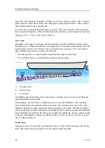
Reducing flow noise
• The shape of the transducer (or dome around it)
must be as streamlined as possible.
• The hull plating in front of the transducer must be
as smooth as possible.
Important
Be especially aware of bilge keels and zinc alloy
anodes. The keel must be rounded off without
sharp edges. Neither extruding objects nor abrupt
transitions must be present.
• Each transducer must be mounted with a small inclination angle (approximately 2
degrees).
Reducing machinery noise
• Each transducer must be installed as far away from the engine room as possible.
• The main engine and relevant auxiliary engines and equipment must be fixed to rigid
foundations to avoid vibrations.
• Any hull structure that may vibrate should be damped or coated to reduce the
vibrations.
The use of shock absorbers or floating rafts may sometimes reduce this noise. The
structure-borne noise may be reduced by isolation, for example by providing vibration
clamping between the transducer and the hull structure.
EA640 Installation Manual
Summary of Contents for EA640
Page 62: ...62 413764 B 388697 WBT outline dimensions EA640 Installation Manual ...
Page 63: ...413764 B 63 Drawing file ...
Page 64: ...64 413764 B 400930 WBT Cabinet outline dimensions EA640 Installation Manual ...
Page 65: ...413764 B 65 Drawing file ...
Page 66: ...66 413764 B EA640 Installation Manual ...
Page 67: ...413764 B 67 Drawing file ...
Page 93: ......
Page 94: ... 2018 Kongsberg Maritime ...


