50
413764/B
An Ethernet switch is required if more than one WBT is used.
A junction box is required if the transducer cable is longer than provided.
List of cables
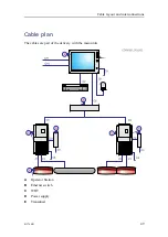
A set of cables is required to connect the EA640 units to each other, and to the relevant
power source(s).
Cable
Type
From/To
Minimum requirements
C1
Transducer cable
From WBT to transducer
*
C2
DC power cable
From Power supply to WBT
**
C3
AC power cable
From Power supply to AC power
outlet
**
C4
Ground cable
From WBT to vessel ground
1 x 6 mm
2
C5
Ethernet cable
From WBT to Ethernet switch
CAT5–E STP
C6
Ethernet cable
From Operator Station to
Ethernet switch
CAT5–E STP
C7
Computer cable
From Operator Station to
keyboard
**
C8
Computer cable
From Operator Station to mouse
(or another similar device)
**
C9
Ground cable
From Operator Station to vessel
ground
1 x 6 mm
2
C10
AC power cable
From Operator Station to AC
power outlet
**
Comments
1
The transducer cable is provided with the transducer. If you need to splice
the transducer cable to make it longer, observe the information in the end user
documentation for the relevant transducer.
2
The cable is supplied with the EA640 delivery.
Identifying EA640 cables on a project cable drawing
The EA640 is often a part of a project delivery. For such deliveries, specific project cable
drawings are established to show all the main cables, and how the various products
are connected. In such project cable drawings, the EA640 cables may be identified
as
EA640/Cx
.
EA640 Installation Manual
Summary of Contents for EA640
Page 62: ...62 413764 B 388697 WBT outline dimensions EA640 Installation Manual ...
Page 63: ...413764 B 63 Drawing file ...
Page 64: ...64 413764 B 400930 WBT Cabinet outline dimensions EA640 Installation Manual ...
Page 65: ...413764 B 65 Drawing file ...
Page 66: ...66 413764 B EA640 Installation Manual ...
Page 67: ...413764 B 67 Drawing file ...
Page 93: ......
Page 94: ... 2018 Kongsberg Maritime ...


