58
413764/B
Cable drawings and specifications
Topics
Auxiliary connector for synchronization, page 59
RS-232 used as synchronization trigger (input or output), page 60
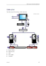
Transducer
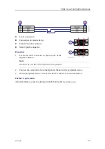
For an EA640 system the WBT can handle up to four channels.
A
Transducers
B
Optional junction box
C
WBT transceiver, connector P1
D
WBT transceiver, connector P2
E
The cable screen must be terminated in the cable gland
If you need to splice the transducer cable, we strongly recommend the use of a metal
junction box with proper cable glands. The cable screen must be connected to the cable
glands. The cable screen and the junction box chassis must not be connected to vessel
ground. Avoid ground loops. You must use the same type of cable as the original
transducer cable, contact Kongsberg Maritime for advice.
EA640 Installation Manual
Summary of Contents for EA640
Page 62: ...62 413764 B 388697 WBT outline dimensions EA640 Installation Manual ...
Page 63: ...413764 B 63 Drawing file ...
Page 64: ...64 413764 B 400930 WBT Cabinet outline dimensions EA640 Installation Manual ...
Page 65: ...413764 B 65 Drawing file ...
Page 66: ...66 413764 B EA640 Installation Manual ...
Page 67: ...413764 B 67 Drawing file ...
Page 93: ......
Page 94: ... 2018 Kongsberg Maritime ...

