background image

86

413764/B

Note

Unless otherwise specified, transducers and hydrophones must not be stored in
temperatures below −10°C and above +50°C.

EA640 Installation Manual

Summary of Contents for EA640

Page 1: ...A640 Hydrographic single beam echo sounder The information is intended for qualified personnel such as shipyard engineers and skilled workers Caution The EA640 echo sounder must never be powered up when the ship is in dry dock The transducer will be damaged if it transmits in open air To prevent inadvertent use of the EA640 disconnect the mains power whenever the vessel is in dry dock ...

Page 2: ...designed Improper use or maintenance may cause damage to the equipment and or injury to personnel You must be familiar with the contents of the appropriate manuals before attempting to operate or work on the equipment Kongsberg Maritime disclaims any responsibility for damage or injury caused by improper installation use or maintenance of the equipment Disclaimer Kongsberg Maritime AS endeavours t...

Page 3: ...ut installation drawings 19 Tools equipment and consumables required for EA640 installation 19 Where to install the transducer 20 Introduction to transducer location 20 Mount the transducer deep 20 Avoid protruding objects near the transducer 21 Keep the transducer far away from the propellers 22 Mount the transducer at a safe distance from bow thruster s 22 Summary and general recommendations 22 ...

Page 4: ...gs and specifications 58 Transducer 58 Auxiliary connector for synchronization 59 RS 232 used as synchronization trigger input or output 60 DRAWING FILE 61 388697 WBT outline dimensions 62 400930 WBT Cabinet outline dimensions 64 TECHNICAL SPECIFICATIONS 68 Performance specifications 69 Interface specifications 70 Weight and outline dimensions 73 Power requirements 73 Environmental specifications ...

Page 5: ...d workers electricians qualified engineers and naval architects You must also be familiar with the installation of electronic and mechanical products Online information For information about the EA640 and other products from Kongsberg Maritime visit our website https www km kongsberg com Registered trademarks Observe the registered trademarks that apply Windows is a registered trademark of Microso...

Page 6: ...640 Topics System description page 7 System diagram page 8 System units page 9 Scope of supply page 11 Installation requirements page 13 Network security page 14 Support information page 16 EA640 Installation Manual ...

Page 7: ...cludes all external input sensor data for replay purposes A highly flexible processing regime makes it possible to log high density complex raw data for advanced post processing We recommend using an additional external storage device You can set up the display to suit your special needs You can choose different presentations on the screen for echograms digital depth and other features Save user s...

Page 8: ...es are not shown The basic EA640 Hydrographic single beam echo sounder consists of one transducer and one WBT Additional transceivers and transducers can be added to meet your operational and functional requirements You also need a computer and a display These can be delivered by Kongsberg Maritime or bought separately A Operator Station B Ethernet switch C WBT D Transducer EA640 Installation Manu...

Page 9: ...e Band Transceiver WBT comprises a rugged box providing all necessary transmitter and receiver electronics The receiver is designed for low noise and it can handle input signals spanning a very large instantaneous dynamic amplitude range A high quality Ethernet cable connects the Wide Band Transceiver WBT to the Operator Station The distance between the Operator Station and the transceiver can be ...

Page 10: ...and accurate single beam transducers for underwater mapping applications A large number of operational frequencies is available For more information about Kongsberg Maritime transducers see our website https www km kongsberg com The installation of the transducer or transducers is not described in detail in this manual See the documentation provided with each transducer EA640 Installation Manual ...

Page 11: ...e included WBT 1 WBT 1 Power supply 1 Power cable 1 4 pin ConX connector For battery or UPS 1 Ethernet cable 1 6 pin PCB connector 2 4 pin PCB connectors 1 Panel cover 2 Cable glands For cables with diameter 8 12 mm 3 Cable glands For cables with diameter 5 5 9 5 mm 3 Blind plugs 4 Nuts Transducers A large range of transducers is available for the different operational frequencies For order number...

Page 12: ...sberg Maritime representative for information about the current model that is delivered with your EA640 system Operational software Operational software is provided on a suitable media If the Operator Station is purchased from Kongsberg Maritime the operational software is installed on the Operator Station and ready for use End user documentation End user documentation is provided on paper and or ...

Page 13: ...ply Voltage requirement 115 230 VAC 47 to 63 Hz single phase nominal Maximum voltage deviation 15 Maximum transient 20 of nominal voltage recovery time 3 s Power consumption 100 VA Approximately Cables and wiring requirements Correct wiring is crucial for the operational performance of the EA640 All cables running between system cabinets located in different rooms and or on different decks must be...

Page 14: ...s best as possible Note It is especially important that the propeller s are not pitted or damaged Network security If a EA640 system is connected to a local area network data security is important Equipment manufactured by Kongsberg Maritime is frequently connected to the vessel s local area network LAN When you connect a computer to a local area network you will always expose the data on that com...

Page 15: ...work This is a task for the network responsible person on board Some key elements here must be The same anti virus protection on all computers including routines for updating this protection The same settings for the firewall on all computers Controlled physical access to computers on the network Trusted and trained operators Log in access mechanisms Same policy for attaching peripheral equipment ...

Page 16: ... of all our offices is provided on our website You can also contact our main support office in Norway Company name Kongsberg Maritime AS Address Strandpromenaden 50 3190 Horten Norway Telephone 24h support 47 33 03 24 07 Website https www km kongsberg com E mail address km hydrographic support kongsberg com EA640 Installation Manual ...

Page 17: ...ons Topics Installation summary page 18 About installation drawings page 19 Tools equipment and consumables required for EA640 installation page 19 Where to install the transducer page 20 Acoustic noise page 25 Preparations ...

Page 18: ...stallation The installation shipyard must provide all necessary design and installation drawings as well as the relevant work standards and mounting procedures If required all documents provided by the shipyard for the physical installation of the EA640 must be approved by the vessel s national registry and corresponding maritime authority and or classification society Such approval must be obtain...

Page 19: ...drawings of the relevant compartment Lines plan Tools equipment and consumables required for EA640 installation In order to do the EA640 installation all necessary tools and equipment for mechanical work cabinet installation and electrical wiring must be available It is not practical to provide a detailed list of all necessary tools and equipment You must be equipped with a standard set of tools T...

Page 20: ...as general advice Each EA640 installation must be handled separately depending on the hull design and the other electrical and mechanical systems installed on the vessel Mount the transducer deep In order to achieve the best possible EA640 performance mount the transducer as deep as possible under the vessel s hull There are several reasons for this recommendation Flow noise Consider the situation...

Page 21: ...transducer as deep as possible on the hull Note Kongsberg Maritime AS takes no responsibility for any damages to the transducer the cable or the mounting arrangement caused by slamming Avoid protruding objects near the transducer Objects protruding from the hull will generate turbulence and flow noise This will reduce the EA640 performance Protruding objects may be zinc anodes transducers or even ...

Page 22: ...m echo sounder useless almost no matter where the transducer is installed When the bow thrusters are not in operation the tunnel creates turbulence If your vessel is pitching the tunnel may be filled with air or aerated water in the upper position and release this in the lower position In general the transducer should therefore be placed well away from the bow thruster s However this is not an inv...

Page 23: ...f the vessel hull has a bulbous bow this may well be a good transducer location but also in this case the flow pattern of the aerated water must be taken into consideration The foremost part of the bulb is often a good location A Thruster B Transducer location This applies to the vessel in normal trim and speed Preparations ...

Page 24: ...s when the vessel is moving at normal speed Do not place a transducer in the vicinity of protruding objects and especially not close behind them Make sure that the surface of the resulting installation is as smooth and streamlined as possible EA640 Installation Manual ...

Page 25: ...y factors during our product development while our end user documentation aims to help the user to make the right filter settings during operation As for the target properties there is nothing any of us can do with those The signal to noise ratio however can be improved by making the correct choices during installation Signal to noise ratio often abbreviated SNR or S N is a measure used in science...

Page 26: ...ther hydroacoustic systems B The transducer cable is long and may pick up electric noise from generators pumps cooling systems and other electric or electromechanical devices C The preamplifiers are very sensitive and they can easily pick up electrical noise from internal and external power supplies The preamplifiers are also vulnerable for analogue noise created by their own electronic circuitry ...

Page 27: ...l regulations and certifications are used to control and reduce this but even these are limited if the electrical systems are poorly installed and or maintained Propeller noise Propeller noise is often the main source of noise at higher vessel speeds Variable pitch propellers or fast moving propellers usually make more noise than fixed propellers or slow moving propellers Propeller noise is usuall...

Page 28: ...arallel movement of the water The turbulent flow is a disorderly flow pattern full of eddies A Turbulent flow B Laminar flow C Air bubbles Air bubbles absorb and reflect the sound energy and they may in worst cases block the sound transmission altogether The boundary layer increases in thickness when it becomes turbulent The boundary layer is thin in the forward part of the vessel hull and increas...

Page 29: ...a limiting factor to the performance of sonars and echo sounders The ambient noise may be split up as follows Sea noise Air bubbles seismic disturbances waves boundary turbulence etc Biological noise Fish mammals Man made noise Other vessels interference Precipitation noise Heavy rain or hail In some areas where many vessels operate together the engine and propeller noise from other vessels may be...

Page 30: ... separately depending on the hull design and the other electrical and mechanical systems installed on the vessel Reducing flow noise The shape of the transducer or dome around it must be as streamlined as possible The hull plating in front of the transducer must be as smooth as possible Important Be especially aware of bilge keels and zinc alloy anodes The keel must be rounded off without sharp ed...

Page 31: ...rations Reducing interference Interference from the transmission pulses from other hydroacoustic instruments on board the vessel is difficult to avoid The problem may be reduced by choosing the working frequencies carefully and to some extent by separating the different transducers On vessels with a large number of separate hydroacoustic systems installed and in simultaneous use a separate synchro...

Page 32: ...Installing a commercial computer page 35 Mounting the WBT Cabinet page 37 Mounting the drawers in the WBT Cabinet page 39 Designing manufacturing and mounting the steel conduit page 41 Installing the transducer s page 43 Installing the transducer on a blister or drop keel page 44 Installing the transducer on a steel hull page 46 EA640 Installation Manual ...

Page 33: ...ounted anywhere on board the ship provided that the location is dry and ventilated The length of the transducer cables limits where the WBT can be installed The unit can be mounted in any direction and on any surface provided that the environmental requirements are met Note If you mount the WBT on a bulkhead position the unit so that all the connections are facing down Procedure 1 Place the WBT in...

Page 34: ...This 19 cabinet holds maximum seven WBTs with power supplies as well as an Ethernet switch and a power distribution panel Each WBT is then installed on a dedicated WBT Drawer in the rack A Mounting bolts for the WBT B Mounting bracket for the power supply C Holes for fastening and securing the cables D Mounting bolts for the drawer assembly E Mounting bolts for the drawer Procedure 1 Place the WBT...

Page 35: ...quipment A suitable location for the computer must be defined prior to installation Observe the compass safe distance Context For installation of a commercial computer refer to the manual supplied by the manufacturer Note Make sure that the chosen computer meets the EA640 requirements The design and construction must allow for marine use and the computer must be able to withstand the movements and...

Page 36: ...ailable for easy access 3 Make sure that the chosen location meets the installation requirements 4 Provide ample space around the computer You must be able to reach and use the front and rear mounted connectors and devices It is also important that you allow for easy access to all the cables and enough space for inspection maintenance and parts replacement If relevant make sure that the space allo...

Page 37: ...etized to protect your equipment The following specific tools are required for this task Power drill Welding equipment We recommend that you install the WBT Cabinet before you install the WBT Drawers and the transceivers Context The cabinet is mounted on the shock absorbers It is mounted on the deck and secured against a bulkhead Alternatively you can place it next to other similar cabinets and us...

Page 38: ...operation the weight will compress the bottom shock absorbers slightly You must take this into consideration when you plan the mounting b Determine the location of the unit c Verify that the location meets the sonar room requirements d Verify that the location meets the environmental requirements defined for the EA640 e Verify that the location is within range of the transducer cables f Verify tha...

Page 39: ...a Remove the four lifting lugs b Mount the top shock absorber assembly using two of the same holes c Use spare bolts to close the remaining lifting lug holes 6 Place cabinet in its correct position on the bottom frame a Use four bolts through the bottom frame to secure the cabinet b Mount the top shock absorbers to the bulkhead support bracket s 7 Fasten the earth strap Mounting the drawers in the...

Page 40: ... cables D Mounting bolts for the drawer assembly E Mounting bolts for the drawer Procedure 1 Decide where in the cabinet you wish to mount the drawers 2 Mount each drawer using six bolts on each side D 3 Pull out the drawer 4 Remove the power supply bracket B 5 Place the power supply on the drawer and mount the bracket B to secure it 6 Mount the WBT using the bolts provided A Further requirements ...

Page 41: ...f the vessel Prerequisites To design manufacture and mount the steel conduit the following prerequisites must be met All relevant vessel and transducer drawings must be available All relevant work instructions procedures and standards must be available The physical location of the transducer has been determined The installation method has been determined The cable gland has been installed All rele...

Page 42: ... for obtaining and paying for such approval Important Finalize the steel conduit installation before you pull the transducer cable through it Make sure that there are no spatter sharp edges or protruding objects that can damage the transducer cables If a cable is damaged and penetrated by water the transducer may be damaged beyond repair Procedure 1 Based on the vessel drawings the physical proper...

Page 43: ...quisites To get a full overview of the installation you need all relevant vessel drawings You also need the drawings provided for each transducer Context Necessary information for the installation of each transducer can be found in the end user documentation provided with the transducer Procedure 1 Determine the physical location of the transducer The decision must be based on The vessel drawings ...

Page 44: ...lation ship yard Prerequisites The physical location of the transducer has been determined The steel conduits are installed A suitable fairing is designed and mounted Note Whenever relevant all drawings as well as the physical installation of each device must be approved by the vessel s national registry and corresponding maritime authority and or classification society The following special tools...

Page 45: ...keel Use Loctite 290 to secure the bolts 4 Fill the two bolt holes in the transducer with a suitable filling compound putty and smooth out the surface of the transducer face Any obstructions cracks dents or unevenness on the transducer face may cause flow noise 5 When the transducer has been fastened inspect the plating around the transducer face Important Make sure that the surface of the transdu...

Page 46: ...tional registry and corresponding maritime authority and or classification society The following special tools are required for this installation Torque wrench for the mounting bolts Loctite 270 permanent high strength threadlocker Context It is very important that the fairing designed for the installation supports the full length of the transducer body Incomplete support will put the transducer a...

Page 47: ...0 to secure the bolts 4 Fill the two bolt holes in the transducer with a suitable filling compound putty and smooth out the surface of the transducer face Any obstructions cracks dents or unevenness on the transducer face may cause flow noise 5 When the transducer has been fastened inspect the plating around the transducer face Important Make sure that the surface of the transducer face as well as...

Page 48: ...48 413764 B Cable layout and interconnections Topics Cable plan page 49 List of cables page 50 Installing the EA640 cables page 51 Cable drawings and specifications page 58 EA640 Installation Manual ...

Page 49: ...413764 B 49 Cable plan The cables are part of the delivery with the main units A Operator Station B Ethernet switch C WBT D Power supply E Transducer Cable layout and interconnections ...

Page 50: ... cable From Operator Station to keyboard C8 Computer cable From Operator Station to mouse or another similar device C9 Ground cable From Operator Station to vessel ground 1 x 6 mm2 C10 AC power cable From Operator Station to AC power outlet Comments 1 The transducer cable is provided with the transducer If you need to splice the transducer cable to make it longer observe the information in the end...

Page 51: ...ns for this It will make it easier at a later stage to replace the transducer It will protect the cables Noise and interference from other electrical equipment is greatly reduced The risk of flooding is greatly reduced when the steel conduit is terminated above the water line With a steel conduit the installation will satisfy the European Union regulations for electromagnetic compatibility EMC int...

Page 52: ...nel 1 2 Procedure 1 Pull the transducer cable through the steel conduit 2 Make sure that an ample length of the transducer cable is available for maintenance and replacement 3 Cut the transducer cable 4 Find the panel for the rear side of the WBT the cable glands the blind plugs and the nuts EA640 Installation Manual ...

Page 53: ...ind plug to cover the points not in use 7 Pull the transducer cable through the cable glands 8 Remove the insulation on the shield in the transducer cable 9 Cut the shield to just cover the seal 10 Remove the insulation on the wires in the transducer cable 11 Add an end sleeve to the wires 12 Fit the cable gland Cable layout and interconnections ...

Page 54: ...he correct pins in the plugs using the pin out and the ship s cable plan Check the license information to see which transducer to install where 14 Connect the plugs to P1 and P2 15 Make sure the conductive gasket is still attached to the WBT EA640 Installation Manual ...

Page 55: ...age 230 or 115 VAC when connected The output from the power supply is connected to the 12 VDC input socket on the WBT The AC and DC power cables are provided with the power supply Procedure 1 Connect the DC cable from the power supply to the 12 Vdc socket If you wish to operate your WBT from a DC supply you can use any suitable battery providing 12 to 15 Vdc 2 Connect the AC mains plug on the powe...

Page 56: ... the WBTs This gives you only one Ethernet cable from the sonar room to the Operator Station Connecting a synchronization cable to the Operator Station using an RS 232 serial interfaces An RS 232 serial line connection using the Request To Send RTS and Clear To Send CTS signals is common way to connect the EA640 to external devices for synchronisation purposes The cable is connected to the serial ...

Page 57: ... side of the Operator Station Note You must use an RS 232 interface for this purpose 2 Connect the serial cable from the Operator Station to the peripheral device 3 On the peripheral device wire as described in the relevant documentation Further requirements All serial interfaces must be defined in the EA640 software prior to use Cable layout and interconnections ...

Page 58: ...nnector P1 D WBT transceiver connector P2 E The cable screen must be terminated in the cable gland If you need to splice the transducer cable we strongly recommend the use of a metal junction box with proper cable glands The cable screen must be connected to the cable glands The cable screen and the junction box chassis must not be connected to vessel ground Avoid ground loops You must use the sam...

Page 59: ...he manufacturer or purchased from Kongsberg Maritime using order number 387563 Manufacturer Switchcraft Conxall Manufacturer s website http www conxall com Pin number 1 2 3 4 Purpose Future use Synchronization Output Synchronization Input Future use Pin number 5 6 7 Purpose Digital ground Not used Not used Minimum cable requirements Conductors 4 x 0 5 mm2 Screen Overall braided Voltage 60 V Maximu...

Page 60: ... provides interface with any peripheral unit that requires or controls transmit receive synchronization Note that this cable does not support all the signals in the standard RS 232 specification Note This synchronization method can only be used with RS 232 communication You can only connect two systems together Unless otherwise specified this cable must be provided by the installation shipyard Min...

Page 61: ...413764 B 61 Drawing file Topics 388697 WBT outline dimensions page 62 400930 WBT Cabinet outline dimensions page 64 Drawing file ...

Page 62: ...62 413764 B 388697 WBT outline dimensions EA640 Installation Manual ...

Page 63: ...413764 B 63 Drawing file ...

Page 64: ...64 413764 B 400930 WBT Cabinet outline dimensions EA640 Installation Manual ...

Page 65: ...413764 B 65 Drawing file ...

Page 66: ...66 413764 B EA640 Installation Manual ...

Page 67: ...413764 B 67 Drawing file ...

Page 68: ...cal specifications Topics Performance specifications page 69 Interface specifications page 70 Weight and outline dimensions page 73 Power requirements page 73 Environmental requirements page 74 EA640 Installation Manual ...

Page 69: ...ing rate Maximum40 per second Sound Speed Manual 1400 to 1700 m s Calculated from temperature and salinity Calculated from temperature sensor and salinity Read from sound speed probe Interfaces WBT Ethernet communication Optional interfaces Ethernet to ships network Sensors GPS gyro motion speed log temperature remote control annotation water level drop keel external depth and sound speed Export f...

Page 70: ...e and DOP Dilution of Precision string of the NMEA 0183 output NMEA RMC The NMEA RMC datagram transfers the time date position course and speed data from a global navigation satellite system GNSS receiver NMEA VTG The NMEA VTG datagram contains the actual course and speed relative to the ground NMEA ZDA The NMEA ZDA datagram contains the universal time code UTC day month year and local time zone S...

Page 71: ...en you select this protocol the number of sensor variables is fixed and there is no token associated with it Supported datagram formats for annotation data The EA640 supports the following datagram format for annotations Simrad ATS datagram format Simrad ATS is a proprietary datagram format created by Kongsberg Maritime It allows you to import annotations from external devices Supported datagram f...

Page 72: ...nd altitude information SEGY The SEGY sometimes abbreviated SEG Y file format is one of several standards developed by the Society of Exploration Geophysicists SEG for storing geophysical data It is an open standard and is controlled by the SEG Technical Standards Committee For more information see http community seg org XYZ This is processed and interpolated xyz data in ASCII format Note that a n...

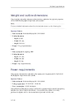
Page 73: ...ongsberg WBT Outline dimensions Depth 213 mm Width 438 mm Height 84 mm Weight 5 kg Approximately Power requirements These power characteristics summarize the supply power requirements for the EA640 Hydrographic single beam echo sounder Operator Station Make and model Hatteland Display JH 19T14 MMC Voltage requirement 115 230 VAC 50 60 Hz Power consumption 100 W maximum The technical specifications...

Page 74: ...40 Hydrographic single beam echo sounder Operator Station Make and model Hatteland Display JH 19T14 MMC Operational temperature 15 to 55 C Storage temperature 20 to 60 C Relative humidity 95 maximum Degree of protection IP66 front IP20 rear The technical specifications are those valid for the computer that may be ordered from Kongsberg Maritime as a part of the EA640 delivery For specifications re...

Page 75: ...ge 76 Lifting units and transportation boxes page 77 Inspection of units and transportation boxes after arrival page 78 Specifications for storage prior to installation or use page 79 Unpacking instructions page 80 Specifications for storage after unpacking page 85 Equipment handling ...

Page 76: ...ons must be investigated by the packer shipper before the unit is dispatched Procedure 1 Ensure that all local transportation is done according to the same specifications as for the initial delivery 2 Make sure that the box containing the unit is kept dry at all times and sheltered from the weather It must not be subjected to shocks excessive vibration or other rough handling The box will normally...

Page 77: ... box or unit before you attempt to lift it 2 Make sure that you have the relevant lifting apparatus required and that this equipment is approved and certified for the load 3 If you need to use a crane a Check the applicable weight certificate for the crane b Check the security of the lifting lugs c If the unit to be lifted is provided with dedicated lifting lugs make sure that all available lugs a...

Page 78: ...plastic bags and or pallets for physical damage Look for signs of dropping immersion in water or other mishandling 2 If external damage is detected open the box to check its contents Request that a representative of the carrier to be present while the box is opened so any transportation damage can be identified and documented 3 If a unit has been damaged prepare an inspection report stating the co...

Page 79: ...s a If a unit is damaged prepare an inspection report stating the condition of the unit and the actions taken Describe the damage and collect photographic evidence if possible Re preserve the equipment b If the unit is not damaged check the humidity absorbing material If required dry or replace the bags then re pack the unit according to the packing instructions 7 If a box has been opened make sur...

Page 80: ...tection the box to be used for storage and transportation must be lined on all walls base and lid using minimum 5 cm thick polyurethane or polystyrene foam Most system units can normally be stored in temperatures between 30 C and 70 C Refer to the relevant technical specifications for details Note Unless otherwise specified transducers and hydrophones must not be stored in temperatures below 10 C ...

Page 81: ...esentative of the carrier to be present while the box is opened so any transportation damage can be identified and documented 3 If a unit has been damaged prepare an inspection report stating the condition of the unit and actions taken Describe the damage and collect photographic evidence if possible Return the inspection report to Kongsberg Maritime as soon as possible 2 Place the box on a stable...

Page 82: ...he weight 2 Lift the unit out of the transportation box 3 Place it in a stable position on the floor work bench 4 Inspect the unit for visual damage 5 Remove any packing material that may be inside the unit 6 Collect and keep the relevant user manuals and or documents provided with the unit Unpacking electronic and electromechanical units Prior to installation or use electronic and electromechanic...

Page 83: ... the unit and actions taken b Describe the damage and collect photographic evidence if possible Return the inspection report to Kongsberg Maritime as soon as possible 4 Assuming all is well open the bag and remove the unit 5 Take out and keep the documentation You will need the documentation if the item shall be returned to us 6 If applicable open the unit and check inside 7 Remove any packing and...

Page 84: ...transducer when it is out of the water Do not lift the transducer by the cable Do not step on the transducer cable Do not handle the transducer roughly and avoid impacts Do not expose the transducer to direct sunlight or excessive heat Do not use high pressure water sandblasting metal tools or strong solvents to clean the transducer face Procedure 1 Obtain the necessary lifting equipment and make ...

Page 85: ...packed These must then be reconnected during the installation procedure Units containing batteries are marked Caution Units containing lithium or alkaline batteries must be handled separately and with care Such units are marked accordingly Do not attempt to recharge such batteries open them or dispose of them by incineration Refer to the applicable product data sheets or battery handling procedure...

Page 86: ...86 413764 B Note Unless otherwise specified transducers and hydrophones must not be stored in temperatures below 10 C and above 50 C EA640 Installation Manual ...

Page 87: ... noise 27 B basic items provided with the delivery 11 block diagram 8 book purpose 5 target audience 5 bow thrusters acoustic noise 22 transducer installation 22 brief description single beam transducer 10 C cabinet WBT Cabinet outline dimensions 64 cable connecting the transducer cable to the transceiver 58 transducer wiring 58 cable conduit designing manufacturing and mounting the steel conduit ...

Page 88: ...w noise 20 28 interference 29 machinery noise 27 propellers 22 27 rattle noise 28 self noise 27 steel conduit for transducer cables 51 system 7 transceiver 9 diagram connections 49 wiring 49 dimensions HOS 73 technical specifications 73 transceiver 73 WBT Cabinet 64 Wide Band Transceiver WBT 62 73 documents download from website 5 download documents from website 5 drawing serial line cable used fo...

Page 89: ...drawers in the WBT Cabinet 39 mount the transducer 44 46 mount the WBT Cabinet 37 transport Kongsberg Maritime equipment 76 unpack a hydrophone 83 unpack a mechanical unit 82 unpack a sonar head 83 unpack a transducer 83 unpack an electronic or electromechanical unit 82 unpack standard parts and units 81 visual inspection of units and transportation boxes after arrival 78 hull surface protruding o...

Page 90: ...irements 73 power consumption computer 73 transceiver 13 74 Transceiver Unit 13 74 Wide Band Transceiver WBT 13 74 power mains tolerances 13 power requirements computer 73 transceiver 13 74 Transceiver Unit 13 74 Wide Band Transceiver WBT 13 74 procedure connecting a synchronisation cable to the computer 56 connecting AC mains to the transceiver 55 connecting AC mains to the Transceiver Unit 55 co...

Page 91: ...ription 10 size HOS 73 technical specifications 73 transceiver 73 Wide Band Transceiver WBT 73 slamming transducer 21 sonar head unpacking 83 specifications interface capabilities 70 outline dimensions 73 performance 69 serial line cable used for synchronization 60 storage after unpacking 85 storage prior to installation 79 weight 73 speed information datagram formats 70 standard computer installa...

Page 92: ...8 transducer cables protection in steel conduit 51 steel conduit 51 transducer connector Wide Band Transceiver WBT 51 transportation of delicate and fragile equipment 76 turbulence protruding objects 21 U unpacking a hydrophone 83 a mechanical unit 82 a sonar head 83 a transducer 83 an electronic or electromechanical unit 82 instructions 80 standard parts and units 81 transducer 44 46 V visual ins...

Page 93: ......

Page 94: ... 2018 Kongsberg Maritime ...

Reviews: