background image

922-20207011/1.0

97

Drawing file

Summary of Contents for Flexview

Page 1: ...Installation Manual Flexview Multibeam Sonar ...

Page 2: ......

Page 3: ...l Release 1 0 This manual provides you with the basic information required to install the Kongsberg Flexview Multibeam sonar The information is intended for personnel with basic mechanical skills For information about the practical use of the product refer to the Kongsberg Flexview Reference manual ...

Page 4: ...aintenance may cause damage to the equipment and or injury to personnel You must be familiar with the contents of the appropriate manuals before attempting to operate or work on the equipment Kongsberg Mesotech disclaims any responsibility for damage or injury caused by improper installation use or maintenance of the equipment Disclaimer Kongsberg Mesotech Limited endeavours to ensure that all inf...

Page 5: ...omagnetic compatibility installation guidelines 18 Support information 19 PREPARATIONS 20 Installation summary 21 Tools and equipment required for Flexview installation 22 INSTALLING THE SONAR PROCESSOR 23 INSTALLING THE SONAR HEAD 26 Attaching the Sonar Head to a bracket 27 Installing the sacrificial anode 30 Mounting the Sonar Head 32 CABLE LAYOUT AND INTERCONNECTIONS 35 Read this first 36 Cable...

Page 6: ...ing that all hardware is properly installed 78 Verifying that all Flexview cables are properly connected 79 Turning on the Flexview 81 Configuring the Flexview for normal operation 82 Setting the Sonar Processor to High Performance 83 Installing the Flexview software 84 Defining the IP address on the Sonar Processor network adapter 85 Testing the Flexview operational functionality 86 Testing opera...

Page 7: ...nts 108 EQUIPMENT HANDLING 110 Transporting Kongsberg Mesotech equipment 111 Lifting units and transportation boxes 112 Inspection of units and transportation boxes after arrival 113 Specifications for storage prior to installation or use 114 Unpacking standard parts and units 115 Repacking the Sonar Head 117 Installation Manual ...

Page 8: ...6 922 20207011 1 0 Flexview ...

Page 9: ...es are also recommended License information The Flexview Software is included with the Flexview system and updates are available free of charge and can be downloaded from http www km kongsberg com mesotechsoftware Software version This Flexview Installation Manual complies with Flexview software version 1 0 Registered trademarks Observe the registered trademarks that apply Windows is a registered ...

Page 10: ...view Topics System description page 9 System diagram page 10 System units page 11 Scope of supply page 14 General safety rules page 17 Installation requirements page 18 Support information page 19 Flexview Installation Manual ...

Page 11: ...ects at a long range whereas a high frequency transducer provides high resolution images at short range Multibeam sonars have an array of transducers that simultaneously transmits pings sound pulses at a specified frequency to cover a large area in less time than a single beam transducer To generate data computer software assigns a colour range corresponding to the amount of sound reflected off a ...

Page 12: ...main components of a basic Flexview system Only the main connections between the units are shown Detailed interface capabilities and power cables are not shown A ROV Topside Unit B Sonar Processor C ROV Junction Box MUX D Flexview Sonar Head Flexview Installation Manual ...

Page 13: ...922 20207011 1 0 11 System units Topics Sonar Processor page 12 Power supply page 12 Sonar Head page 13 Flexview ...

Page 14: ...tandard Ethernet cable If you purchase a computer locally make sure that the chosen model meets the functional and technical requirements The computer must be designed for rugged use and the construction must be able to withstand the vibrations and movements of a vessel Related topics Minimum computer requirements page 108 Power supply The Sonar Head requires a DC power supply to run Normally the ...

Page 15: ...ere The Sonar Head includes transmit and receive transducers and the electronics to generate the transmit pulse and digitize the received signal The sonar data is sent to the Sonar Processor using a standard Ethernet link Caution The Sonar Head s black polyurethane transducer is delicate Avoid impacts to the transducer when installing or handling the Flexview Prolonged exposure to ultra violet ray...

Page 16: ... delivery make sure that the following items are included In the box Flexview Sonar Head Accessory Kit 15 foot cable whip Laminated Quick Start Guide Operational software The Flexview Software can be downloaded from our website https www km kongsberg com mesotechsoftware If the Sonar Processor is purchased from Kongsberg Mesotech the operational software is installed on the Sonar Processor and rea...

Page 17: ...esotech may provide a suitable computer Consult your local dealer or agent for more information Mounting bracket The Sonar Head is designed to attach to a mounting bracket You will need a mounting bracket that attaches to the Flexview The type of mounting bracket you need depends on how you intend to deploy the sonar You can order a mounting bracket from Kongsberg Mesotech or you can make your own...

Page 18: ...ay Kongsberg Mesotech may provide a suitable display Consult your local dealer or agent for more information Uninterruptible Power Supply UPS It is important to ensure continuous operation of the Flexview independent of varying quality of the vessel s mains supply Uninterruptible power supply units are not included in the standard Flexview delivery These items must be purchased locally Several com...

Page 19: ...work on the Flexview system Use the main circuit breaker and label the breaker with a warning sign that informs others that maintenance or installation work is in progress on the system For safety reasons two persons must always be present during troubleshooting with power ON Read and understand the applicable first aid instructions related to electric shock Whenever maintenance is in progress it ...

Page 20: ... Correct installation is required to maintain electromagnetic compatibility Employ the following recommendations to ensure the best EMC performance Use only Kongsberg specified cables and check that any ferrite suppression filters fitted on the cables are installed as per the installation drawings Suppression ferrites are important for minimizing electromagnetic interference If one has to be remov...

Page 21: ... electrical marine vessel codes Note Where the implementation of these recommendations is not possible maintain the maximum practical separation between system components and any other electrical radio equipment operation on the vessel Support information If you need technical support for your Flexview you must contact your local dealer or our support department If you require maintenance or repai...

Page 22: ...20 922 20207011 1 0 Preparations Topics Installation summary page 21 Tools and equipment required for Flexview installation page 22 Flexview Installation Manual ...

Page 23: ...ry important that the installation procedures in this manual are complied to You must do the tasks in the order they are described Procedure 1 Splice the supplied cable whip to the cable leading to your ROV junction box 2 Install the Sonar Processor 3 Install the Sonar Head a Unpack the Sonar Head b Attach the Sonar Head to a bracket c Install a sacrificial anode d Mount the Sonar Head onto your R...

Page 24: ...ipper a soldering iron etc Each tool must be provided in various sizes We recommend that all tools are demagnetized to protect your equipment Specific tools and consumables you will need for the Flexview installation are included in the supplied accessory kit The following tools and items are required for the Flexview installation and are not included in the standard delivery You must purchase the...

Page 25: ...it the available cable lengths between the computer and the other units it connects to Caution Ensure electronic components are free from condensation before turning on Condensation can occur when transitioning from a cool air conditioned environment to a hot and humid environment such as outside on an open boat These parts should also be protected from coming into contact with water sea spray etc...

Page 26: ...truction must allow for marine use and the computer must be able to withstand the movements and vibrations normally experienced on a vessel Verify that you have easy access to cables and connectors and that the computer can be installed in a safe and secure way Standard office computers may not be well fitted for maritime use The motions and vibrations experienced on a vessel may reduce the comput...

Page 27: ...d allows for the physical vibration movements and forces normally experienced on a vessel 2 Select the power cord with the appropriate local plug and connect it to the AC to DC Sonar Processor power supply 3 Connect the AC to DC power supply to the Sonar Processor 4 Connect the mouse to a USB port on the Sonar Processor Note When you connect the cables make sure that they are all properly secured ...

Page 28: ...26 922 20207011 1 0 Installing the Sonar Head Topics Attaching the Sonar Head to a bracket page 27 Installing the sacrificial anode page 30 Mounting the Sonar Head page 32 Flexview Installation Manual ...

Page 29: ...epending on the chosen installation method additional tools may be required You will need a mounting bracket that attaches to the Flexview The type of mounting bracket you need depends on how you intend to deploy the sonar You will need to install the four plastic shoulder washers and plastic isolation pad found in your Sonar Head accessory kit These parts are used to protect the Sonar Head from c...

Page 30: ...te Avoid impacts to the transducer when installing or handling the Flexview Prolonged exposure to ultra violet rays and excessive heat may damage the surface of the polyurethane transducer face Always store the Flexview in the provided equipment case when not in use If the Flexview is mounted on an ROV cover the transducer when not in use Flexview Installation Manual ...

Page 31: ...ad lining it up with the mounting holes Note Ensure the Sonar Head connector is pointing in the right direction so that the cable connecting the Sonar Head to the other system units is routed correctly 5 Secure the Sonar Head to the bracket B with the provided short screws Caution Marine grade grease or anti seize compound included must be applied to all fasteners during assembly Do not use excess...

Page 32: ...ochemical process where one metal corrodes anode at a greater rate than the other cathode while in an electrolyte solution Seawater is an excellent electrolyte and will sustain galvanic currents over significant distances In seawater and in combinations with other metals aluminium is the most likely metal to become the anode The aluminium Sonar Head has a protective anodizing layer added during th...

Page 33: ...tion between the anode and the Sonar Head a Measure the connection between the new anode and the metal base of the Sonar Head power telemetry connector Alternatively measure the connection between the anode and one of the stainless steel fasteners screwed into the housing If an electrical connection is not being made the anodizing layer may be present inside the threaded mounting holes To connect ...

Page 34: ...set of tools This tool set must comprise the normal tools for mechanical tasks This includes different screwdriver types pliers adjustable spanners etc Depending on the chosen installation method additional tools may be required You will need a mounting bracket that attaches to the Flexview Ensure the anode and isolation pad are properly installed to prevent the Sonar Head s aluminium housing from...

Page 35: ...nsducer face In addition the water in front of the Sonar Head should not be aerated Tip When installing the Flexview on an ROV tilting the Sonar Head down around 8 to 15 may improve detection of the sea bottom at short range Procedure 1 Attach the bracket assembly to your desired mounting location using either a pre configured or custom orientation a To view and configure the pre configured orient...

Page 36: ...Positive roll means starboard side down Positive yaw means starboard turn 2 Measure the distance between the Sonar Head and your GPS or other position sensor You will need to measure the distance in terms of the Flexview coordinate system as shown in the image The coordinate system s Master Reference point is always assumed to be your GPS or position sensor reference point X to starboard Y forward...

Page 37: ... page 36 Cable plan page 37 VDSL cable plan page 39 List of Flexview cables page 40 Focal multiplexer compatibility table page 41 Installing the Flexview cables page 42 Cable drawings and specifications page 66 Basic cable requirements page 71 Cable layout and interconnections ...

Page 38: ...ied by Kongsberg Mesotech as a part of the Flexview delivery Kongsberg Mesotech Limited accepts no responsibility for damage to the system or reduced operational performance when this is caused by improper wiring Note Before you install or maintain the Flexview cables make sure that the AC mains circuit breaker for the system is switched off Flexview Installation Manual ...

Page 39: ...th the main units This diagram shows two deployment examples 1 Basic system interconnection for setting up a bench test for example 2 Remotely Operated Vehicle ROV system interconnection A Sonar Processor B Mouse C Flexview Power Supply Cable layout and interconnections ...

Page 40: ...011 1 0 D Sonar Head E ROV Topside Unit F ROV Controller G ROV Junction Box MUX Note When deployed on an ROV the ROV Junction Box normally supplies power to the Sonar Head 12 to 36 VDC Flexview Installation Manual ...

Page 41: ...is diagram shows two deployment examples 1 Basic system interconnection for setting up a bench test for example 2 Remotely Operated Vehicle ROV system interconnection A Sonar Processor B Mouse C Flexview Power Supply D Sonar Head E VDSL Modem F ROV Topside Unit Cable layout and interconnections ...

Page 42: ...in DC connector on Flexview cable breakout box Flexview Power Supply C3 Ethernet Umbilical Telemetry connector RJ 45 female socket on Flexview cable breakout box ROV Junction Box MUX Sonar Processor ROV Topside Unit C4 Ethernet Flexview Cable Flexview cable breakout box Sonar Head C5 Flexview cable whip spliced with ROV whip ROV Junction Box MUX Sonar Head C6 Sync whip Four pin Sync VDSL connector...

Page 43: ...onds to link after 7 attempts at gigabit speed 907 GEM Yes Requires 907 DIAG E to remove 1000 BASE T negotiation setting 907 E Yes The 625M version works out of the box The 2 5G version must have 1000 BASE T negotiation setting disabled either via the GUI or via the dipswitches on the board This applies to both remote and console boards to ensure both sides are linked at 100 Mbps 914 HDE Yes You m...

Page 44: ...based contact cleaner isopropyl alcohol or liquid soap and hot water Do not use acetone gasoline or similar products Context SubConn cable connectors can be mated above water dry mate or underwater wet mate Caution Always apply grease before mating Observe these cable handling rules Disconnect by pulling straight not at an angle Do not pull on the cable Avoid sharp bends in cables Connectors shoul...

Page 45: ...in transparent layer of grease on the face of the connector A If mating underwater make sure that all sockets are completely sealed B 4 Fully mate the male and female connector to secure optimal distribution of grease on pins and in sockets Remove any excess grease from the connector joint 5 Make sure that the grease has been sufficiently applied Note If mating underwater you can skip this step a ...

Page 46: ...44 922 20207011 1 0 Related topics Sonar Head SubConn MCIL8F Power and Ethernet page 69 Flexview Installation Manual ...

Page 47: ...telemetry errors if the cable is not terminated correctly Gigabit Ethernet cables must be terminated to a much higher standard than RS232 422 485 serial cables Prerequisites The following tools and parts are used when splicing a subsea cable A Round cable stripper such as the Jonard CST 1900 B Side cutters C Wire strippers D Utility knife E Soldering iron with damp sponge F Heat shrink tubes G Hot...

Page 48: ...pside equipment or ROV Tip Before you start place your soldering iron in its stand plug it in and preheat it so that it will be ready to use later Please observe the following safety precautions when performing this procedure Make sure your work area is free from any debris that may prove flammable Make sure your work area is well ventilated Do not inhale the fumes from the solder Keep loose hair ...

Page 49: ...eight of the cable stripper blade so that it will slice through the cable jacket only and not the inner wires c Spiral the cable stripper around the cable in a circular motion to slice the cable jacket Cable layout and interconnections ...

Page 50: ...48 922 20207011 1 0 d Use the side cutters to cut off the sliced cable jacket 2 Prepare the wires on both cables for soldering Flexview Installation Manual ...

Page 51: ...oloured Ethernet pairs are twisted around each other and how the twist ratio is different for each Ethernet pair The two twisted wires assist in decreasing crosstalk When splicing try to keep the pairs twisted together in the same way Caution Do not untwist the pairs more than 0 5 for 100 Mbps or 0 375 for 1000 Mbps A pair untwisted more than half an inch can adversely affect the performance of th...

Page 52: ...all incision with the side cutters then peel off the rest by hand d Using the side cutters cut each Ethernet pair to a different length so that there will be a 1 4 spacing between each wire splice This spacing is necessary so that the wire splices are not all bunched together causing a bulge in the cable Flexview Installation Manual ...

Page 53: ...y 1 4 of insulation from each wire Tip Make sure you match the gauge of the wire with the appropriately sized hole on the wire stripper or you may cut both insulation and wire 3 Solder the wires and cover the wire splices with heat shrink Cable layout and interconnections ...

Page 54: ...he ends of the wires Called tinning the tips this process improves conductivity and makes soldering both quicker and easier b Using the side cutters cut the heat shrink tubes to the right size Allow for at least a 1 4 overlap over the existing insulation Flexview Installation Manual ...

Page 55: ...hem when soldering in the next step Try to twist the Ethernet pairs as they were originally d Refer to the cable pinout diagrams for both cables to identify which wires to solder together Tip Ethernet pair colours may differ from cable to cable depending on the cable manufacturer Use the pinout diagrams to match the pin signal with the colour for each wire Cable layout and interconnections ...

Page 56: ...ponge to wipe off excess solder A vice clamp or tweezers helps to hold the wires in place f Move the heat shrink tubes over to the middle of each join g Use the hot air gun to shrink the tubing 4 Use a cable tester to make sure the electrical connections in the cable are good Flexview Installation Manual ...

Page 57: ... on the female connector For Seacon connectors make sure that the o ring is not missing Line up the pins and tighten the locking sleeve b Detach the wiremap adapter from the cable tester c Plug one of the RJ45 connectors A on a test connector B into the RJ45 socket on the wiremap adapter Note It doesn t matter which cable end you connect to the wiremap adapter Cable layout and interconnections ...

Page 58: ...button to turn on the cable tester f Turn the rotary switch to DISCOVER g Make sure that the wiremap diagram looks good with no open pins in any of the Ethernet pairs Note The wiremap only shows the Ethernet pairs used for data transmission not the two wires that carry electrical current h Turn the rotary switch to AUTOTEST i Press the white TEST button Flexview Installation Manual ...

Page 59: ...ice with the splicing kit a Unpack the contents of the splicing kit WARNING Read all the Material Safety Data Sheet information supplied with the splicing kit before using Contents include a mold a bag of flame retardant compound rubber splicing tape and an abrasive cloth Tip Do not dispose of the cardboard carton you will need it later Cable layout and interconnections ...

Page 60: ...e abrasive cloth scuff the ends of the cable outer jackets c Using the utility knife cut the tapered ends of the mold to fit the cable diameter d Tape the spliced wires together to keep them in position Flexview Installation Manual ...

Page 61: ...the cardboard carton and place the mold s hinge into it The carton will hold the splice in position for compound pouring h Prepare the flame retardant compound Remove the plastic pouch from the paper bag Squeeze the black side of the pouch to a smooth consistency and uniform colour Pull the middle of the pouch apart to break the seal inside Cable layout and interconnections ...

Page 62: ...0207011 1 0 Knead the pouch to mix the contents Important Mix until the colour is completely uniform Do not exceed one minute Squeeze the compound away from the corners of the pouch Flexview Installation Manual ...

Page 63: ... compound into the mold Fill the mold until the compound reaches the mold s filler spout j Allow the compound to cure from 16 to 36 hours depending on the room temperature 6 De mold the cable splice a Remove the splicing tape from the mold ends Cable layout and interconnections ...

Page 64: ... 922 20207011 1 0 b Remove the mold Start by separating the mold halves at the filler spout c Trim off the excess compound from the filler spout by cutting it off at the base Flexview Installation Manual ...

Page 65: ...922 20207011 1 0 63 7 Test the electrical connections again using the cable tester and make sure that it is ready for use Cable layout and interconnections ...

Page 66: ...green in this mode Note DIP switches two three and four have no function in CPE mode 2 When using the Flexview cable with a breakout box connect the supplied RJ11 patch cable from the four pin Sync VDSL Bulgin connector on the breakout box to the RJ11 connector A on the modem If you are integrating the Flexview into an ROV system connect a single twisted pair cable from your ROV topside unit to th...

Page 67: ...e data rate and link performance on cables of different quality and lengths For longer cables you may wish to use a profile with a lower bandwidth such as profile 0 8b or 1 12a Note For more information on setting the VDSL Profile refer to the Flexview Reference Manual Related topics VDSL cable plan page 39 Cable layout and interconnections ...

Page 68: ...11 1 0 Cable drawings and specifications Topics Ethernet cable page 67 VDSL patch cable page 68 Sonar Head SubConn MCIL8F Power and Ethernet page 69 Cable breakout box connectors page 70 Flexview Installation Manual ...

Page 69: ... CAT 6 cables are used in local area networks with bandwidths exceeding 100 Mbit Note It is very important that high quality Ethernet cables are used You must use CAT 5E quality or better If you use cables with lower bandwidth capacity you will reduce the Flexview performance For 100Base TX connections only Orange Orange White Green and Green White are required No cross over is required for 100Bas...

Page 70: ...for Ethernet telemetry The RJ11 plug connects to your VDSL modem Note The breakout box on the Flexview cable includes a 4 pin Bulgin connector for VDSL Only two of these pins are used for VDSL RJ11 connector Pin Functions Pin 1 No connection Pin 2 No connection Pin 3 VDSL Pin 4 VDSL Pin 5 No connection Pin 6 No connection Flexview Installation Manual ...

Page 71: ...tors are a wet mate style and can be mated or unmated at the surface or underwater Pin Functions Pin 1 VIN black and green Pin 2 VIN red and white Pin 3 SYNC VDSL brown white Pin 4 SYNC_GND VDSL white Pin 5 BI_DA orange white TX Pin 6 BI_DA white TX Pin 7 BI_DB green white RX Pin 8 BI_DB white RX Note Flexview supports auto MDI MDI X Related topics Mating the SubConn cable connector page 42 Cable ...

Page 72: ...nd Sync or VDSL A Power 2 pin Bulgin connector B Ethernet RJ45 connector C Sync VDSL 4 pin Bulgin connector Power connector Pin Functions Pin 1 V Pin 2 V Caution Before you apply AC power to any Flexview unit you must verify that the voltage is correct Sync VDSL connector Pin Functions Pin 1 Sync VDSL Pin 2 Sync Ground VDSL Pin 3 No connection Pin 4 No connection Note The Sync VDSL connector allow...

Page 73: ...e properly supported and protected and all relevant precautions must be made to prevent unwanted noise Topics Ethernet cable installation page 72 Radio frequency interference page 73 Physical protection of cables page 73 Grounding of system cables page 74 Cable connections and terminations page 74 Cable layout and interconnections ...

Page 74: ...commended instead of tie wraps and can easily be reused if rearranging the cables Use Category 6A cable This type of cable has a special core wrap that isolates and protects the core from alien crosstalk Cable termination Depending on your deployment method you may need to terminate your Ethernet cables Terminating Ethernet cables is very precise work To avoid impacting telemetry quality take note...

Page 75: ...suitable material In such a situation flexible cables should be screened wherever possible It is important that cables other than those supplying services to the equipment installed in a radio room are not installed through a radio room high power switch gear or other potential sources of interference Cables which must pass through a radio room must be screened by a continuous metal conduit which ...

Page 76: ...ing cables or units Metallic casings pipes and conduits must be grounded and when fitted with joints these must be mechanically and electrically grounded locally Cable connections and terminations All cable connections are shown on the applicable cable plan and or interconnection diagrams Where the cable plan shows cable connections outside an equipment box outline the connections are to be made t...

Page 77: ...ry page 76 Verifying that the Flexview is ready for operational use page 77 Turning on the Flexview page 81 Configuring the Flexview for normal operation page 82 Testing the Flexview operational functionality page 86 Turning off the Flexview page 91 Setting to work ...

Page 78: ...hat all Flexview cables are properly connected 2 Power up the Flexview for the first time 3 Configure the Flexview for operational use a If required set the Sonar Processor to High Performance b If required install the Flexview operational software c If required define the IP address on the Sonar Processor network adapter Note If you have a unique network environment such as an IP Address conflict...

Page 79: ... met All Flexview hardware units have been installed according to the relevant instructions All system cables have been installed All operating power is available All relevant personnel ships electrician and tools for example a voltmeter are available Procedure 1 For each Flexview unit that operates on AC mains a If necessary measure the voltage in the mains outlet b Make sure that the relevant Fl...

Page 80: ...el c Verify that there is adequate ventilation to avoid overheating 2 Perform a close visual inspection of the Power Supply Verify that the unit is suitably oriented to enable easy connection to the Flexview cable and for maintenance 3 Ensure the anode and isolation pad are properly installed to prevent the Sonar Head s aluminium housing from corroding Important You are responsible for protecting ...

Page 81: ...ch cable that is in used on the Flexview a Verify that the cable has been installed according to the cable plan b Verify that the connections made at each end of the cable are correct c Verify that any locally fitted plugs and connectors are suitable for the installation location For example sealed or spark proof connectors should be used in areas where flammable gasses may accumulate d Check that...

Page 82: ...again The resistance should be nearing open circuit f Tell the other person to short the two cores together using the shorting strap g Using your ohmmeter check the continuity again The resistance should now be zero ohms h Tell the other person to remove the shorting strap Verify that the resistance reaches open circuit again i Check each core s resistance to ground and each core s resistance to a...

Page 83: ...ded with an on off switch Procedure 1 Power up the Sonar Head using the power supply Note It may take up to 60 seconds for the Flexview software to connect to the Sonar Head once the power is applied 2 Turn on the Sonar Processor Wait while the operating system loads 3 Log in to Windows 4 Double click the Flexview icon on the Sonar Processor desktop to start the software 5 Once the Flexview softwa...

Page 84: ...e Flexview for normal operation Topics Setting the Sonar Processor to High Performance page 83 Installing the Flexview software page 84 Defining the IP address on the Sonar Processor network adapter page 85 Flexview Installation Manual ...

Page 85: ...ings link on the right side of the window Observe that the Power Options dialog box opens b In the menu on the left select Create a power plan c Select the High performance radio button d Give your new custom plan a name then click Next e Select Never for both Turn off the display and Put the computer to sleep when plugged in f Click Create Tip Once you have created a custom plan you can adjust so...

Page 86: ...ote When running the Flexview software for the first time a Windows Firewall dialog box may appear Allow access for all networks Procedure 1 Launch the installer Flexview_V0100 Setup exe 2 Follow the installation wizard s instructions a When prompted use the default folder location b When prompted check the Create a desktop shortcut box c Click Yes to install the KML USB Converter when prompted an...

Page 87: ...ter in your Sonar Processor you will only need to do this once Procedure 1 On the Sonar Processor close the Flexview software 2 Open the Network Connections dialog box a In the bottom left corner of your desktop select the Windows Start button b On the menu select Settings c Observe that the Settings window opens d Select Network Internet e Select Change adapter options f Select the network adapte...

Page 88: ...ad You can test the operation of the Sonar Head by confirming that sonar data is being correctly displayed in the Information Widget and sonar view In addition any errors will be displayed in the Output Messages or Head Status windows Prerequisites The Flexview software must be running Tip Make sure there is sufficient disk space available to complete the survey Flexview Installation Manual ...

Page 89: ...e sure there are no errors shown in the Output Messages window under the Host Messages or Head Messages tab 4 Make sure there are no errors in the Connection Status and Head Status windows a Click on the text Active located in the lower right corner of the status bar Observe that the Connection Status window opens b Make sure that all items listed under the FlexviewSonar show check marks If any it...

Page 90: ...bottom appears across the entire width of the sonar view If the edges appear weak and profile points are not detected at the edges make sure there are no obstructions preventing the Sonar Head s receive for example proximity to the vessel hull keel Testing the Sonar Head telemetry You can run a telemetry test to make sure the link between the Sonar Head and the Flexview software is working correct...

Page 91: ...in Mbps entered into the box instead of the default speed If the applied override telemetry bandwidth is less than the telemetry bandwidth required by the sonar application range the ping rate is reduced Procedure 1 Click Setup Connect to start the Sonar Head 2 Add the Ethernet Test application to your list of favourite applications a Open the Sonar Apps menu on the top bar then select Customize A...

Page 92: ...is at least 80 Note If the Network utilization is less than 80 disconnect the sonar close all other programs then reconnect the sonar In general make sure that your network environment supports the required link speed e In the Flexview software look for any messages in the Output Messages window Make sure there are no lost packets Tip The contents of the Output Messages window are also saved to a ...

Page 93: ... the Flexview software 2 Switch off the Sonar Processor a Close the Flexview software and any third party software b Shut down Windows 3 Disconnect the power cord leading to the power supply Alternatively switch off the breaker supplying power to the Flexview 4 Switch off any additional items such as a sound velocity profiler or display If required refer to the instructions provided by the product...

Page 94: ...ensions page 96 About the drawings in the drawing file Relevant drawings related to the installation and or maintenance of the Flexview are provided for information purposes only The drawings are not to scale Unless otherwise specified all measurements are in inches The original installation drawings are available by request in PDF and or SolidWorks format Flexview Installation Manual ...

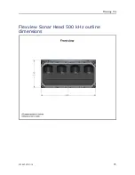
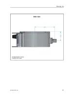
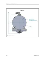
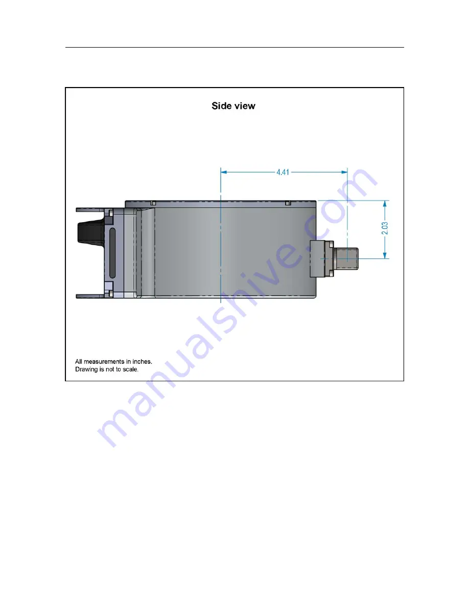
Page 95: ...922 20207011 1 0 93 Flexview Sonar Head 500 kHz outline dimensions Drawing file ...

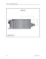
Page 96: ...94 922 20207011 1 0 Flexview Installation Manual ...

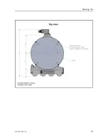
Page 97: ...922 20207011 1 0 95 Drawing file ...

Page 98: ...96 922 20207011 1 0 Flexview Sonar Head 950 1400 kHz outline dimensions Flexview Installation Manual ...

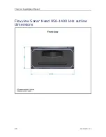
Page 99: ...922 20207011 1 0 97 Drawing file ...

Page 100: ...98 922 20207011 1 0 Flexview Installation Manual ...

Page 101: ...o technical specifications page 100 Interface specifications page 101 Performance specifications page 104 Mechanical specifications page 106 Power requirements page 107 Environmental requirements page 108 Minimum computer requirements page 108 Technical specifications ...

Page 102: ...istics of the Flexview Multibeam sonar It also provides information related to power requirements physical properties and environmental conditions Note At Kongsberg Mesotech we are continuously working to improve the quality and performance of our products The technical specifications may be changed without prior notice Flexview Installation Manual ...

Page 103: ...assigned coordinated universal time UTC of position as well as a selection of position quality factors Supported datagram formats for speed information The Flexview supports the following datagram format for speed information NMEA VTG The NMEA VTG datagram contains the actual course and speed relative to the ground Supported datagram formats for heading information The Flexview supports the follow...

Page 104: ...t Kongsberg EM Attitude 3000 The EM Attitude 3000 is a proprietary datagram format created by Kongsberg for use with digital motion sensors It holds roll pitch heave and heading information The datagram contains a 10 byte message Octans STD1 This is a third party proprietary datagram format for heading speed and motion It was created by iXSea http www ixblue com for use with their Octans gyrocompa...

Page 105: ...nt number of beams Therefore data body size may change depending upon the mode Synchronization PRI Sync PRI Sync set with Trigger Mode on the Sonar Setup page of the System Configuration dialog box provides ping synchronization with another Sonar Head or other acoustic source that supports synchronization for example EK60 Sidescan DVL etc PRI Sync is a level sensitive method of synchronization Whe...

Page 106: ...uired This method is not recommended for Bathymetry applications as it is not accurate enough Note Computer time sync requires both GGA and ZDA input Performance specifications These performance specifications summarize the main functional and operational characteristics of the Flexview system Range 500 kHz 0 2 m to 150 m 950 kHz 1400 kHz 0 2 m to 70 m Coverage 140 Range resolution 1 cm Frequency ...

Page 107: ... Imaging mode 950 kHz Horizontal Field of View 140 Vertical Beamwidth 27 Angular Resolution 0 8 Update rate up to 40 Hz Imaging mode 1200 kHz Horizontal Field of View 75 Vertical Beamwidth 21 Angular Resolution 0 65 Update rate up to 40 Hz Imaging mode 1400 kHz Horizontal Field of View 45 Vertical Beamwidth 18 Angular Resolution 0 55 Update rate up to 40 Hz VDSL Firmware version 1 5 Part number 32...

Page 108: ...mesotechsoftware Mechanical specifications These mechanical specifications summarize the physical properties of the Flexview system Note For more detailed information about the physical dimensions see the Drawing file Sonar Processor The Sonar Processor uses a high quality commercial off the shelf laptop computer workstation The weight and dimensions of the model may vary Contact your Kongsberg Me...

Page 109: ...nn Connector model 8 pin Power requirements These power characteristics summarize the supply power requirements for the Flexview system Sonar Processor Power adapter input voltage 120 240 VAC Laptop input voltage 19 5 VDC 180W max Sonar Head Input voltage 12 to 36 VDC Input power 22W avg peak power 60W mode dependant Maximum cable loop resistance for Sonar Head power 0 1 Ω 12VDC 2 Ω 24VDC 6 Ω 36VD...

Page 110: ...ution The Sonar Head must not be exposed to direct sunlight for prolonged periods of time Prolonged exposure to ultra violet rays and excessive heat may damage the surface of the polyurethane transducer face Store the Sonar Head in a cool dry location away from ozone sources such as electric motors or welders Minimum computer requirements Although a computer can be ordered from Kongsberg Mesotech ...

Page 111: ...The minimum technical requirements are Processor 2 80 GHz Intel quad core i7 Memory minimum 8 GB Hard disk minimum 500 GB Graphics card RAM 256 MB Network interface 100 1000 Mbps Serial interfaces One or more serial line interfaces are required The number of serial lines depends on the interface requirements Operating system The Flexview software has been designed for the Microsoft 64 bit Windows ...

Page 112: ...e 111 Lifting units and transportation boxes page 112 Inspection of units and transportation boxes after arrival page 113 Specifications for storage prior to installation or use page 114 Unpacking standard parts and units page 115 Repacking the Sonar Head page 117 Flexview Installation Manual ...

Page 113: ...units containing certain types of batteries These units must be checked properly and the regulations must be investigated by the packer shipper before the unit is dispatched Procedure 1 Ensure that all local transportation is done according to the same specifications as for the initial delivery 2 Make sure that the box containing the unit is kept dry at all times and sheltered from the weather It ...

Page 114: ... list s Heavy units may be equipped with dedicated lifting lugs for transportation by crane within the workshop or installation area Note Observe the local rules and regulations related to the use of lifting equipment Procedure 1 Check the weight of the box or unit before you attempt to lift it 2 Make sure that you have the relevant lifting apparatus required and that this equipment is approved an...

Page 115: ...nt has been damaged during the transport request that a representative of the carrier is present during the inspection Procedure 1 Check all boxes wooden or cardboard boxes plastic bags and or pallets for physical damage Look for signs of dropping immersion in water or other mishandling 2 If external damage is detected open the box to check its contents Request that a representative of the carrier...

Page 116: ...t so Special circumstances may be suspected damage to the box and its content or inspections by civil authorities a If a unit is damaged prepare an inspection report stating the condition of the unit and the actions taken Describe the damage and collect photographic evidence if possible Re preserve the equipment b If the unit is not damaged check the humidity absorbing material If required dry or ...

Page 117: ... marked for example Must not be transported or stored in temperatures below 5 C Other temperature limits may be used if applicable If a unit needs temperature protection the box to be used for storage and transportation must be lined on all walls base and lid using minimum 5 cm thick polyurethane or polystyrene foam Most system units can normally be stored in temperatures between 30 C and 70 C Ref...

Page 118: ...ble Return the inspection report to Kongsberg Mesotech as soon as possible 2 Place the box on a stable work bench or on the floor with the top of the box facing upwards 3 In the absence of other instructions always open the top of the carton first The contents of the box will normally have been lowered into the carton from above so this will usually be the easiest route to follow Be careful when y...

Page 119: ...ack polyurethane transducer is delicate Avoid impacts to the transducer when installing or handling the Flexview Prolonged exposure to ultra violet rays and excessive heat may damage the surface of the polyurethane transducer face Always store the Flexview in the provided equipment case when not in use Store the Sonar Head in a cool dry location away from ozone sources such as electric motors or w...

Page 120: ...and accessory kit B into the foam insert that sits on top of the Sonar Head Note If you ordered a USB flash drive from Kongsberg Mesotech it goes here too 3 Pack the Quick Start Guide C on top of all other items before closing the lid Note If you purchase cables from Kongsberg Mesotech they will be supplied in separate cases Flexview Installation Manual ...

Page 121: ...ng requirements 74 cable installation requirements 72 cable plan 37 VDSL 39 cable requirements cable 71 cable connections 74 cable terminations 74 grounding 74 physical protection 73 radio frequency interference 73 cable terminations requirements 74 cables connection requirements 74 grounding requirements 74 list of system interconnection cables 40 procedures 45 protection 73 read this first 36 re...

Page 122: ...ts 74 gyro information datagram formats 101 H hardware verify correct installation 78 heading information datagram formats 101 high voltage safety rules 17 how to attach the Sonar Head to a bracket 27 configure the Sonar Processor 83 install the operational software 84 install the sacrificial anode 30 install the Sonar Processor 23 install the VDSL cables 64 lift units and transportation boxes 112...

Page 123: ...drawings about 92 minimum requirements computer 108 motion information datagram formats 102 motion reference unit datagram formats 102 mounting Sonar Head 32 MRU datagram formats 102 N network adapter IP Address 85 IP address for transceiver communication 85 Subnet mask 85 NMEA datagrams depth information 102 GPS information 101 gyro information 101 heading information 101 motion information 102 p...

Page 124: ...ction cable requirements 73 publication purpose 7 target audience 7 purpose power supply 12 Sonar Head 13 Sonar Processor 12 this manual 7 R radio frequency interference cable requirements 73 reader this manual 7 registered trademarks 7 repacking Sonar Head 117 required items not provided with the delivery 15 requirements cable connections 74 cable grounding 74 cable installation 72 cable terminat...

Page 125: ...n specification 103 system description 9 diagram 10 standard tools for installation 22 system cables description 36 list 40 system software installation 84 T target audience this manual 7 technical specifications 100 technical requirements computer 108 technical specifications interface specifications 101 temperature requirements 108 terminations cable requirements 74 testing sonar and sensors 88 ...

Page 126: ... 2019 Kongsberg Mesotech ...

Reviews: